APC 5KVA UPS with NMC 3 giving error; battery charger fault

khamosh

Disciple
Model: APC SURTD5000XLI-CC

So today, it started giving this error; Charger Battery Fault Exists and now it won't switch to direct AC mode.
When resetting it, it goes to AC mode for 5-10 seconds and when it detects the fault, it goes back to inverter mode and starts giving this error.

It is out of warranty. I received a quotation for an extended warranty a few months earlier when my 2 year warranty was about to expire, and it was ₹16,500, including GST, so I skipped it.

This was purchased from a relative for a considerably lesser amount and was using it for my gaming PC and a home NAS.

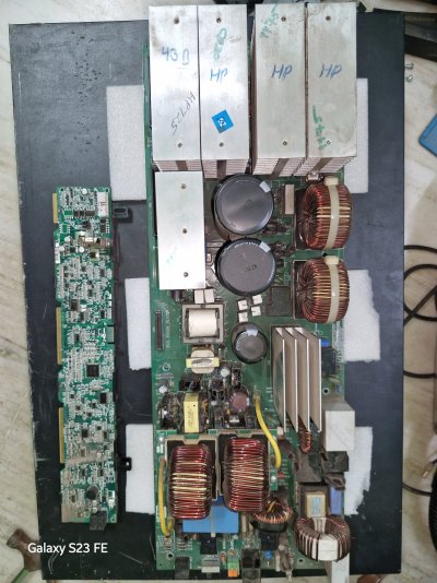
I opened it up. There was dust buildup (a lot of), so I cleaned it to observe any visible defects but couldn't see any.

I tried resetting it, but nothing happened.

I watched some YouTube videos [I watched the HINDI version] and figured out the charger section. I observed it twice, but still, no burst or leakage was found.

What should I do? Although, I live in a tier 2 city, I don't think these kinds of UPS are repaired here.

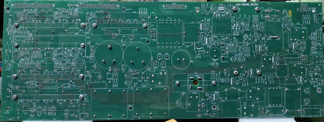
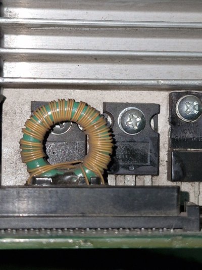
Sharing the PCB picture. If anyone can help, that would be incredible.


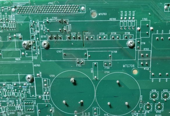
EDIT: Apparently, transistors Q730 has gone bad. How can I confirm this?
 

Attachments

  • 1725648944150269545722494317245.jpg
    1725648944150269545722494317245.jpg
    391.5 KB · Views: 82
  • 20240907_030532.jpg
    20240907_030532.jpg
    262.1 KB · Views: 69
  • 20240907_030157.jpg
    20240907_030157.jpg
    342.8 KB · Views: 68
Last edited:
How do you speculate that these have gone bad?
I saw a YouTube video of a Pakistani guy this morning. Got his Whatsapp number in the comments, I asked him on WhatsApp and got this reply: "Check fuses F3 and F4 with Q730 and Q731. These are used in the charger portion."

I checked them and replied with the readings, so he told me to replace Q730 with a similar specs transistor.

I want to get a second opinion now.
 
These can be checked in circuit but that will be little bit advance.

Usually it requires shorting base/gate pin of the transistor with emitter/source pin and observe voltage on collector/drain pin, the voltage should rise, then connecting positive supply on base/gate through a 1k resistor the voltage on the collector/drain pin should fall. These have to be done when the board is powered on. This is only one test that I know, there might be others.

Also if you somehow source an another working board like this, then yours can be repaired, it becomes real easy when you give a working board along with a non working board to a repair man, but I suppose chances of that happening is nil.

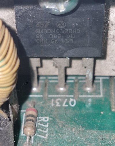
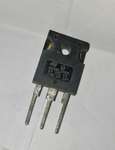
First you have to get the part number from the transistor, for that you have to remove the heatsink I think. Through this we can see what kind of transistor it is and we will also know the exact pinouts, then you can look for replacement.

You can also try finding the schematic of this board online, it will be helpful for the repair guy.
 
First you have to get the part number from the transistor, for that you have to remove the heatsink I think. Through this we can see what kind of transistor it is and we will also know the exact pinouts, then you can look for replacement.

You can also try finding the schematic of this board online, it will be helpful for the repair guguy.
I googled the part number and got its datasheet, its a 30A 1200v IGBT transistor. But, its of Q731 and I've to replace Q730. I think both of them are same.
I don't have access to Q730 and can't check its part number as its blocked by another component [transformer ig]

Also, this pakistani guy told me to replace the fuses F703 and F704
 

Attachments

  • 20240907_062924.jpg
    20240907_062924.jpg
    278.5 KB · Views: 50
  • 20240907_182252.jpg
    20240907_182252.jpg
    362.9 KB · Views: 57
  • STGW30NC120HD.PDF
    122.5 KB · Views: 27
Last edited:
This is a very common repair for UPSs, most places replace them with pin-compatible alternatives that's rated for the same (operating) voltage if they can't find the exact part.

This is an extremely high quality UPS so I would pay the official service center for the repair. I know Vertiv does out-of-warranty repairs so APC should as well.

If I didn't already have an overkill setup, I'd be pestering you to buy this off of you, haha.
My city's service center is temporarily closed and a third party is asking me to purchase an extended warranty for ₹16,500 [more than what I paid for this UPS] I'm not willing to spend this much, I'd rather get a pure sine wave inverter and battery.
So it's an IGBT, they are rare compared to the usual bjt and mosfets. I do see some replacements on mouser, but they cost between 500-1000 per piece.

This might help.

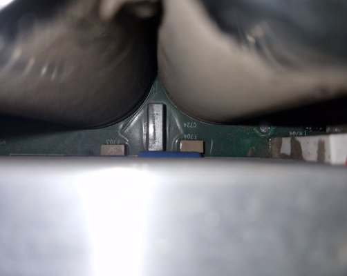
I got this replacement transistor [not exact match] for ₹220 but couldn't find the fuse. This Pakistani guy is an expert in these kinds of UPSs [see YouTube link provided earlier]. He told me to replace both fuses [F703 & F704]. Now, fuse is hiding between the two large capacitors and charger heatsink, so I can't see its part number. However, this paki guy told me to use any 3A 250V (rectangular) fuse. I couldn't find this in the local market.

Please link me to one.

Also, planning to get an inverter and battery.
A store quoted me ₹8k for Exide 12V 1625 and ₹20k for 230/250Ah [don't remember] battery. The shop owner said that it'll take a load of 1200W. Is this official specification? I tried looking up the official specs, but I couldn't find any mention of wattage on their official website.
 

Attachments

  • 20240907_203844.jpg
    20240907_203844.jpg
    230.8 KB · Views: 49
  • Fuse F703 F704.jpg
    Fuse F703 F704.jpg
    169.3 KB · Views: 50
Last edited:
A store quoted me ₹8k for Exide 12V 1625

1625VA means around 975W assuming 60% efficiency factor like in a typical ups. However, why do you even want to get exide ups when there are much more well known home ups brands like microtek & luminous.
 

1625VA means around 975W assuming 60% efficiency factor like in a typical ups. However, why do you even want to get exide ups when there are much more well known home ups brands like microtek & luminous.
He was offering one from microtek too, lower priced than Exide [42 month warranty], should I consider that?
Although, He insisted on 80% efficiency in these, but I don't belive him

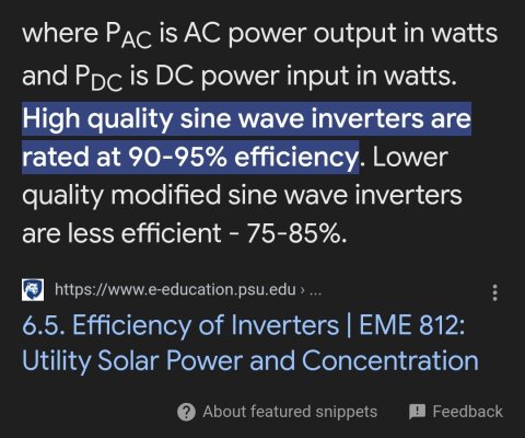
Edit: Found this when googled(see pic)
So, I can assume atleast 70% efficiency must be there
 

Attachments

  • Screenshot_20240908_095618_Chrome.jpg
    Screenshot_20240908_095618_Chrome.jpg
    285.4 KB · Views: 52
Last edited:
He was offering one from microtek too, lower priced than Exide [42 month warranty], should I consider that?
Definitely, Microtek is far more established brand when it comes to home inverter but make sure it is pure sine wave model as non pure sine wave models are just a bit cheaper but because of extra commission the shopkeepers push them on unsuspecting/not knowledgeable customers. Another thing to consider is the after sales support, not all brands provide home visit support for home inverter in every location.

Edit: Found this when googled(see pic)
So, I can assume atleast 70% efficiency must be there
Looks alright.
 
Definitely, Microtek is far more established brand when it comes to home inverter but make sure it is pure sine wave model as non pure sine wave models are just a bit cheaper but because of extra commission the shopkeepers push them on unsuspecting/not knowledgeable customers. Another thing to consider is the after sales support, not all brands provide home visit support for home inverter in every location.


Looks alright.
Both of them were pure sine wave inverters
 
Any inverter under ~30k would be a toy compared to what this UPS is capable of. This kind of UPS sells for over 50k new without batteries and is around 90% efficient.

The only downside is that number of batteries it needs, but you can work around that by getting smaller or used batteries. 4x 26Ah batteries are usually much cheaper than a single 100Ah battery while giving you the same capacity.

Sunrom.com has the box fuses you need, you can solder them on the underside without removing the old ones, if they've failed open (no continuity).
 
Sunrom.com has the box fuses you need, you can solder them on the underside without removing the old ones, if they've failed open (no continuity).
Ordered, thanks

Also, continuity (beep) is in both the fuse but it is showing some resistance, when I conveyed this reading [326, 740] to paki guy, he asked me to replace both of them
The only downside is that number of batteries it needs, but you can work around that by getting smaller or used batteries.
Exactly, it requires 16 sealed lead acid batteries (internal). I have frequent power cuts here and due to this, the battery connected to the fuse [inside a battery pack] degrades much faster than the others. This overall reduces backup, increases charging time and distorted information on NMC regarding remaining backup time

I got a whole battery replacement under warranty and it degraded again in eight months.

I am curious to know if it would be a good idea to get a separate inverter and battery, then connect this UPS (if repair is successful) to the inverter. Then I could replace the single degraded battery of the UPS to prevent further degradation.

Just wondering, UPS has a comparatively lesser switching time than an inverter. So when there's a power cut and the UPS detects that the inverter is providing no power (while switching to battery) for that 10-15ms, the UPS switches to battery and then again after this very short delay (10-15ms) switches back to power from the inverter (from battery).
Will this affect the internal components of the PCB in the UPS?
I don't know if I explained it correctly what was going on in my mind.
 
Last edited:
Will this affect the internal components of the PCB in the UPS?
I suppose it will, but how much degradation on components you can't really tell, this is APC, it is meant to do this, perhaps some other component fails before the switching components. But if longevity is a concern then I would put more attention on keeping the unit cool.
 
Any inverter under ~30k would be a toy compared to what this UPS is capable of. This kind of UPS sells for over 50k new without batteries and is around 90% efficient.

The only downside is that number of batteries it needs, but you can work around that by getting smaller or used batteries. 4x 26Ah batteries are usually much cheaper than a single 100Ah battery while giving you the same capacity.

Sunrom.com has the box fuses you need, you can solder them on the underside without removing the old ones, if they've failed open (no continuity).
Got the replacement parts. The PCB is thick af, so I don't think I'll be able to replace it myself. Is it a good idea to place both the fuses and transistors and solder them in parallel without removing the bad ones to check if it's working? Could it damage other parts? Or in general will it work as intended?
 
Is it a good idea to place both the fuses and transistors and solder them in parallel without removing the bad ones to check if it's working?
Not a good idea. Right tool for the job is electric vacuum desoldering iron, but I don't know if it's worth it to spend 700-800 for this tool to remove 3-4 components.
 
Not a good idea. Right tool for the job is electric vacuum desoldering iron, but I don't know if it's worth it to spend 700-800 for this tool to remove 3-4 components.
Thanks for the suggestion. I used one of those cheap, non-electric suction ones.
This will be useful to me.
 
. I used one of those cheap, non-electric suction ones.
Those are good if you have access to the pad from both the sides of the board, so on one side you can use the normal iron to heat the pad, and then from the other side use the desolder tool to suck all the solder. If you try to do this dual action on the same side, by the time you switch to desolder tool the solder joint will harden again, to compensate for this you will have to heat the pad a lot more, but that is bad for the pcb and surrounding components.

But if you can't access both the sides, the electric desolder is very handy. It is very similar to the non-electric one but has the heating iron built in to melt the solder. So you just load the pump -> touch the joint -> wait 1-2 second -> click -> remove.

1726204101460.png
 
Last edited:
Back
Top