Probably a sign that pursuing a DIY repair is not feasible anymore, ha.
Do both mosfets have the same pin assignment?
He replied and said to replace both IGBTs and fuses
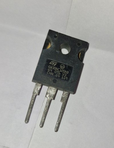
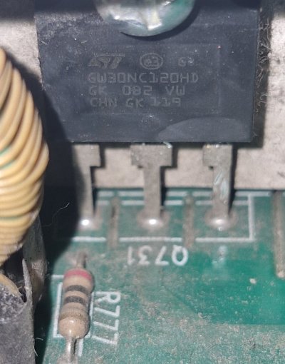
Both mosfets have the same part number but are not exact copies of each other [see picture]
If you had access to a DC variable power supply, you could put in another fuse, inject voltage into the circuit with a low current limit, spray 99% isopropyl alcohol on the pcb and see where it evaporates fastest as a crude proxy for temperature. That should show you the shorted component. It's a common diagnostic method for YT repair guys.
But I've never done voltage injection or repaired a UPS before, so don't take my advice.
I know this can be a thrilling experience, but I will stay away from it for now. Also, I don't have access to a variable power supply. Thanks for this information.
So both fuses were showing resistance earlier and you replaced them and now one of them is blown?
I hope you replaced them with correct current rating.
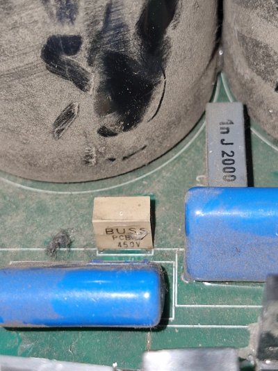
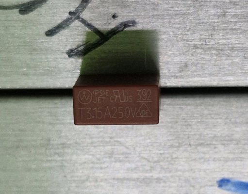
Yes both fuses F703 and F704 were blown replaced with 250v 3.15A instead of the 450v [see pic]
What was the resistance they were showing earlier?
I didn't replaced them but soldered them under side of the board,
Prior to replacement, F703 showed 740 while F704 showed 326 and now after the new one burst F704 is showing 364
The new transistor that you replaced, did you know about it's pinouts? You made sure that is has same pin outs as the original one?
Both mosfets have the same part number but are not exact copies of each other [see picture]
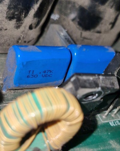
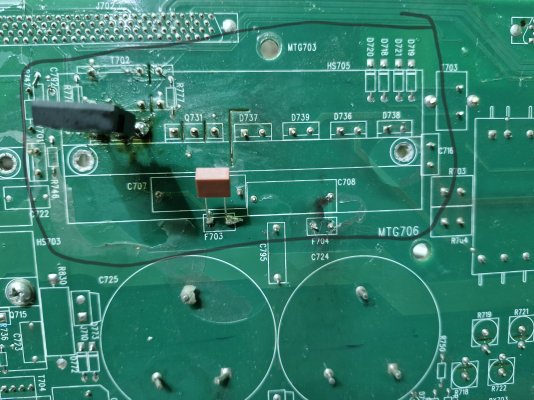
Now this pakistani guy asked me to replace both mosfets and both the fuses so while doing so I tested the capacitors beside them and one of them [C708, this sits along with F704] seems to have gone bad (no resistance, see pic) and I'm not sure that this was the case before installing the fuses (or I may be tripping)
Edit: Sorry for the ignorance guys, but it was the loose cables that restricted the AC power. My bad. Now it's fixed, and now it shows the error (battery charger fault exists) once again.
The highlighted part in the last picture is the charger section and it doesn't have much components.
I will get another MOSFET and replace the other one. I will also try to get the blue capacitor from the market (pls link me if available online).
Could someone please link me to the exact replacement fuse(450V from the picture)? That would be helpful.