APC 5KVA UPS with NMC 3 giving error; battery charger fault

Got the replacement parts. The PCB is thick af, so I don't think I'll be able to replace it myself. Is it a good idea to place both the fuses and transistors and solder them in parallel without removing the bad ones to check if it's working? Could it damage other parts? Or in general will it work as intended?

For the three pin parts, you'll need to cut the pins of the existing ones before you try this. It can work, without any load connected of course, just for testing purposes (a few seconds). The fuses can be mounted on the reverse side with proper insulation in a semi-permanent state.

However, it shouldn't cost more than Rs 100 or Rs 50 for a repair technician to do these replacements for you. If you don't have inverter/UPS repair stores nearby then you could try amplifier repair places, every city/town/village should have one of those.

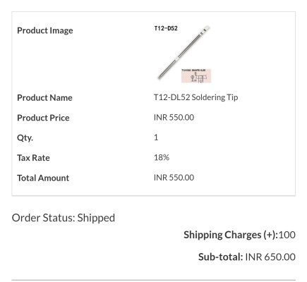
That desoldering iron is pretty useful, I got one a few weeks ago — I feel like I should've gotten it decades earlier. I got mine from Toolworld.in
 
I bought two T12 tips from them, both appear to be original Hakko even though they're not listed as Hakko bits. They've been in daily use for a couple of years now.

edit: Attached screenshots @variablevector

The DL52 tip is for bios chip extraction and the BC3 is for general purpose soldering.
 

Attachments

  • Screenshot_2024-09-14-07-27-23-673_com.microsoft.emmx-edit.jpg
    Screenshot_2024-09-14-07-27-23-673_com.microsoft.emmx-edit.jpg
    98.5 KB · Views: 31
  • Screenshot_2024-09-14-07-27-05-064_com.microsoft.emmx-edit.jpg
    Screenshot_2024-09-14-07-27-05-064_com.microsoft.emmx-edit.jpg
    96.2 KB · Views: 28
  • Screenshot_2024-09-14-07-26-48-319_com.microsoft.emmx-edit.jpg
    Screenshot_2024-09-14-07-26-48-319_com.microsoft.emmx-edit.jpg
    108.1 KB · Views: 34
Last edited:
I bought two T12 tips from them, both appear to be original Hakko even though they're not listed as Hakko bits. They've been in daily use for a couple of years now.

edit: Attached screenshots @variablevector

The DL52 tip is for bios chip extraction and the BC3 is for general purpose soldering.
Thanks! I already have a very fine tip, not sure what its name is. I'll get the BC3 for general purpose stuff and maybe the KF for anything larger.
 
However, it shouldn't cost more than Rs 100 or Rs 50 for a repair technician to do these replacements for you. If you don't have inverter/UPS repair stores nearby then you could try amplifier repair places, every city/town/village should have one of those.
I have repair shops here, but it would be a mess to reassemble the ups and carry the whole (too heavy) for repair and then ask the technician to disassemble it again.
I was thinking of testing it myself first and if it doesn't work, I'll carry the whole system to a repair shop for further diagnosis.

Now, I think I'll only carry the PCB, get the pieces replaced, get back home and test if they work.

I also called up official APC support and they assigned a technician from another city to visit me. This technician called today to inform me that they do not do repairs and only replace parts. Since it is a single PCB system, the entire PCB would have to be replaced. So, I asked for the cost and he said he would inform me after checking. He has not called me since then.

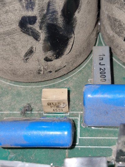
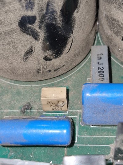
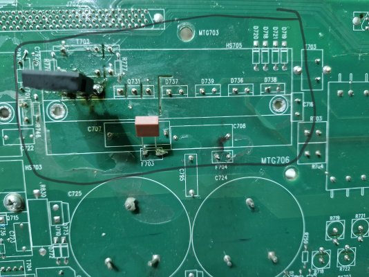
Edit: So, I soldered the transistor and removed the previous one. I also managed to remove the heatsink. To my surprise, the fuse is 450V. Then, I asked this Pakistani guy, and he said to proceed anyway, so I did. When I supplied power, there was no reaction (unusual: no fan started, no relay click sound). So, I cold started the UPS and in a few seconds, I heard a bursting sound. I waited a while, turned it off, and checked. Fuse F704 has blown and F703 is still good.
What should I conclude from this?
 

Attachments

  • 20240914_205839.jpg
    20240914_205839.jpg
    354.9 KB · Views: 29
Last edited:
If the fuse blew with the new mosfet then there's another fault somewhere, probably a bad capacitor or some debris causing a short.

It's also possible a coil or another component has shorted. Follow the traces connected to the fuse and test for shorts on any component along the way.

Now, I think I'll only carry the PCB, get the pieces replaced, get back home and test if they work.

Yes, that is what I do.
 
If the fuse blew with the new mosfet then there's another fault somewhere, probably a bad capacitor or some debris causing a short.

It's also possible a coil or another component has shorted. Follow the traces connected to the fuse and test for shorts on any component along the way.


Yes, that is what I do.
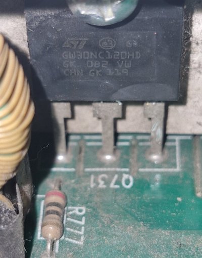
It is just my understanding that F703 is for Q730 and F704 is for Q731. Now, both fuses were replaced because they were showing resistance. Replacing the MOSFET did not solve the issue and instead gave me another problem (UPS showing no sign of AC power, thus no error of battery charger). Now, F703 is still good and only F704 is showing resistance. Can it be possible that either the new MOSFET is not compatible or is not good? Thus F703 didn't blow up

Also, now this pakistani guy is leaving my messages on seen :p
 
If you had access to a DC variable power supply, you could put in another fuse, inject voltage into the circuit with a low current limit, spray 99% isopropyl alcohol on the pcb and see where it evaporates fastest as a crude proxy for temperature. That should show you the shorted component. It's a common diagnostic method for YT repair guys.

But I've never done voltage injection or repaired a UPS before, so don't take my advice.
 
So both fuses were showing resistance earlier and you replaced them and now one of them is blown?

I hope you replaced them with correct current rating.

What was the resistance they were showing earlier?

Well, there are too many variables now, there is definitely a short somewhere and is drawing extra current.

Can it be possible that either the new MOSFET is not compatible or is not good?
The new transistor that you replaced, did you know about it's pinouts? You made sure that is has same pin outs as the original one?

I wish we had schematics.

The voltage injection pointed by @variablevector is probably the next step.

Don't procced any further, the thing involves AC voltage and we don't want you get zapped by it.
 
Probably a sign that pursuing a DIY repair is not feasible anymore, ha.

Do both mosfets have the same pin assignment?
He replied and said to replace both IGBTs and fuses
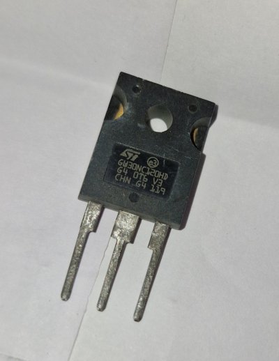
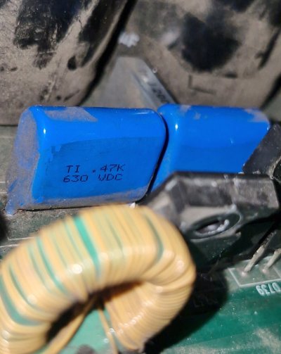
Both mosfets have the same part number but are not exact copies of each other [see picture]
If you had access to a DC variable power supply, you could put in another fuse, inject voltage into the circuit with a low current limit, spray 99% isopropyl alcohol on the pcb and see where it evaporates fastest as a crude proxy for temperature. That should show you the shorted component. It's a common diagnostic method for YT repair guys.

But I've never done voltage injection or repaired a UPS before, so don't take my advice.
I know this can be a thrilling experience, but I will stay away from it for now. Also, I don't have access to a variable power supply. Thanks for this information.
So both fuses were showing resistance earlier and you replaced them and now one of them is blown?

I hope you replaced them with correct current rating.
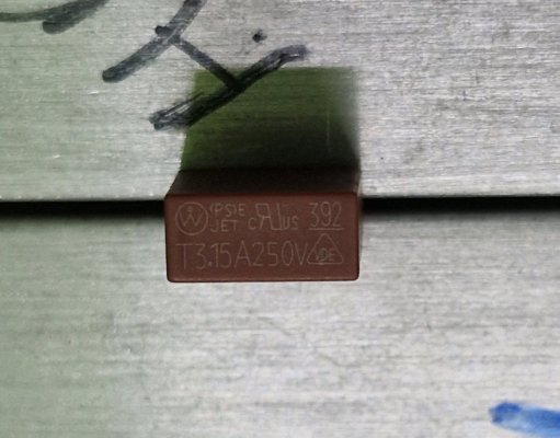
Yes both fuses F703 and F704 were blown replaced with 250v 3.15A instead of the 450v [see pic]
What was the resistance they were showing earlier?
I didn't replaced them but soldered them under side of the board,
Prior to replacement, F703 showed 740 while F704 showed 326 and now after the new one burst F704 is showing 364
The new transistor that you replaced, did you know about it's pinouts? You made sure that is has same pin outs as the original one?
Both mosfets have the same part number but are not exact copies of each other [see picture]

Now this pakistani guy asked me to replace both mosfets and both the fuses so while doing so I tested the capacitors beside them and one of them [C708, this sits along with F704] seems to have gone bad (no resistance, see pic) and I'm not sure that this was the case before installing the fuses (or I may be tripping)

Edit: Sorry for the ignorance guys, but it was the loose cables that restricted the AC power. My bad. Now it's fixed, and now it shows the error (battery charger fault exists) once again.

The highlighted part in the last picture is the charger section and it doesn't have much components.

I will get another MOSFET and replace the other one. I will also try to get the blue capacitor from the market (pls link me if available online).
Could someone please link me to the exact replacement fuse(450V from the picture)? That would be helpful.
 

Attachments

  • 20240907_203844.jpg
    20240907_203844.jpg
    230.8 KB · Views: 23
  • 20240907_062924.jpg
    20240907_062924.jpg
    278.5 KB · Views: 21
  • 20240915_195347.jpg
    20240915_195347.jpg
    218.5 KB · Views: 21
  • 20240914_210903.jpg
    20240914_210903.jpg
    242.1 KB · Views: 25
  • 20240914_205839.jpg
    20240914_205839.jpg
    354.9 KB · Views: 23
  • 20240915_200833.jpg
    20240915_200833.jpg
    347.3 KB · Views: 19
Last edited:
What should I conclude from this?
What you should conclude, is to not mess with power electronics you do not understand. Diagnosing electronics is hard, even more so when done remotely based off just photos and description. If the IGBT and the fuse failed, was it just them or are they just symptom to the real problem, like shorted transformer windings? I'm not trying to put you down, but what you're doing (asking for advice, replacing suspect parts) are fine when dealing with low voltage/power stuff and you particularly don't care about daily usage. But this is power electronics, that too an UPS, which you probably plan to use regularly. I would either give it to APC for repair, or call it a day.
 
One good thing about APC is that there is lot of protection built in, there are fuses at multiple places, so if some fault occurs it shuts that whole section down, it has full blown CPU card doing all sorts of measurements, as soon as it detects some fault it, it turns off everything and puts the machine into bypass mode and generates error codes based on that.

I have a feeling it is still repairable considering that the following information is widely available, someone somewhere should be able to repair. The guy explained every section of this board nicely.


The two JFET's are switching a boosted 400v positive and negative supply, and they are indeed part of the charging section. Whatever paki guy you are talking to is spot on, on pointing you into the right section and the crucial parts. It's just that there might some other problem and I think it is in the charging section.

Edit: Sorry for the ignorance guys, but it was the loose cables that restricted the AC power. My bad. Now it's fixed, and now it shows the error (battery charger fault exists) once again.
So all hope is not lost, imagine you being able to fix this thing on your own, the amount of adrenaline rush you will get and the satisfaction. :)
 
Last edited:
What you should conclude, is to not mess with power electronics you do not understand. Diagnosing electronics is hard, even more so when done remotely based off just photos and description. If the IGBT and the fuse failed, was it just them or are they just symptom to the real problem, like shorted transformer windings? I'm not trying to put you down, but what you're doing (asking for advice, replacing suspect parts) are fine when dealing with low voltage/power stuff and you particularly don't care about daily usage. But this is power electronics, that too an UPS, which you probably plan to use regularly. I would either give it to APC for repair, or call it a day.
I think I know why the charger stopped working. It's because I never cleaned the heatsinks. Also, I added an additional battery pack APCRBC140 [older battery pack which was replaced under warranty] and didn't configure or inform the UPS of this change. That's my fault. Perhaps UPS was providing power for the single pack to charge and that led to some defect.

Yes, I should proceed with care with these electronics and I don't cross my limits. I do proper research and have guidance. I like DIY and have been doing a lot of stuff.
Repair guys locally will see this kind of stuff for the first time and APC is asking me to replace the charger [single PCB board i.e the only PCB] and it's out of warranty. Repair guys in my city wouldn't care and would just say that parts are not available; they wouldn't go online searching for the parts.

I understand that you stated the above with a sense of care, but as a 27 year old, I don't need any schooling on what's dangerous and what's not.

By making the above statement, you are demotivating others who are trying to help, and that is unacceptable.
 
Last edited:
I understand that you stated the above with a sense of care, but as a 27 year old, I don't need any schooling on what's dangerous and what's not.

By making the above statement, you are demotivating others who are trying to help, and that is unacceptable.
As long as you understand the risks. Peace.
 
I think I know why the charger stopped working. It's because I never cleaned the heatsinks. Also, I added an additional battery pack and didn't configure or inform the UPS of this change. That's my fault. Perhaps UPS was providing power for the single pack to charge and that led to some defect.
You are correct, the guy in the video has another video saying that the charging section of this board is only suitable for the battery that comes inbuilt. If you add extra batteries that section will over work to charge them all. He is talking about charging them externally. So there might be a separate device that is used to charge your additional battery pack.
 
You are correct, the guy in the video has another video saying that the charging section of this board is only suitable for the battery that comes inbuilt. If you add extra batteries that section will over work to charge them all. He is talking about charging them externally. So there might be a separate device that is used to charge your additional battery pack.
I have seen these videos and also referenced them in earlier posts.
Yes, this person suggests an external charger for an additional battery pack SURT192XLBP (highly rated, 4 modules of batteries), but that is altogether a different situation.
What I did was connect the older spare internal battery pack (less rated, 2 modules of batteries) that was replaced under warranty, for a higher backup time.

The control card was unaware of the additional battery and limited its charging to match only the internal battery pack, leading to internal charging failure after a year of usage in this configuration.

Edit: At this point, I'm desperate to repair it or have it repaired since the inverter and battery I got can't keep up when I'm gaming, and my MSI PSU trips. It works fine under normal loads.
I wasn't aware of this issue with inverters.
 
Last edited:
The control card was unaware of the additional battery and limited its charging to match only the internal battery pack, leading to internal charging failure after a year of usage in this configuration.
Is there a setting somewhere to tell the control card that you added extra battery.

I think whether the extra battery is 2 module or 4 module, it's still seems too much for the internal charging circuit.
 
Is there a setting somewhere to tell the control card that you added extra battery.
Yes, this can be done through the NMC (Network Management Card) portal or by connecting to the serial com port on the rear of the UPS
I think whether the extra battery is 2 module or 4 module, it's still seems too much for the internal charging circuit.
Using an external charger was his personal view.
APC officially never recommends using an external charger to charge an external battery pack.

I just had to update this on the control card, which I didn't do because when I added it, the control card thought that an official 4 module external battery pack was connected, but I was using the 2 old internal ones.
 
Back
Top