Absolutely. Addressable LEDs are much easier to set up and control. That said, they do come with a few drawbacks.
Yeah, the ESP8266 is significantly faster, more capable, and cheaper these days.
I got most of mine from Robu. The Nano currently goes for around ₹200, and the DIP ATmega328P is about ₹300. I remember picking them up for ~₹200 back in the day.
The ATmega line is still popular because of its simplicity. If you need precise timing control, ATmega datasheets are way easier to understand compared to most other microcontrollers.
Plus, their power consumption is excellent in low-power modes.
If anyone’s interested in learning assembly, ATmega is a great place to start.
99.9% people here come from reddit, because they want to buy and sell PC stuff.
Exactly! the vibe is great.
This subsection is bound to grow, mods are doing an excellent job running things here.
Big players like Robu do have their own forums, but they don’t come close to the quality of interaction here.
There are other communities too, but most are too narrowly focused on specific areas of electronics.
Even though its costly mmwave sensors were a good choice for that. I have tried couple of those rcwl-0516 radars. They are way better than average pir sensors but still need little motion occasionally to detect presence.
I’ll see if I can post one of my mods of ikea air quality sensor vindriktning. Its basically adding D1 mini into the housing and collecting the measurements periodically. Last I checked the sensor was on sale for 400-500.
It’s not the most accurate one but its better than nothing and it does reliably light up when something is cooking in the kitchen. So, you know if not hazardous gasses it helps detect other allegedly hazardous items at home
Yes exactly!
when they launched it, I tried a bit to make it lively but soon realized that a forum that is so closely tied to brands and the delicate relationship that comes along will never be a good place to have an open, lively discussion among other stuff
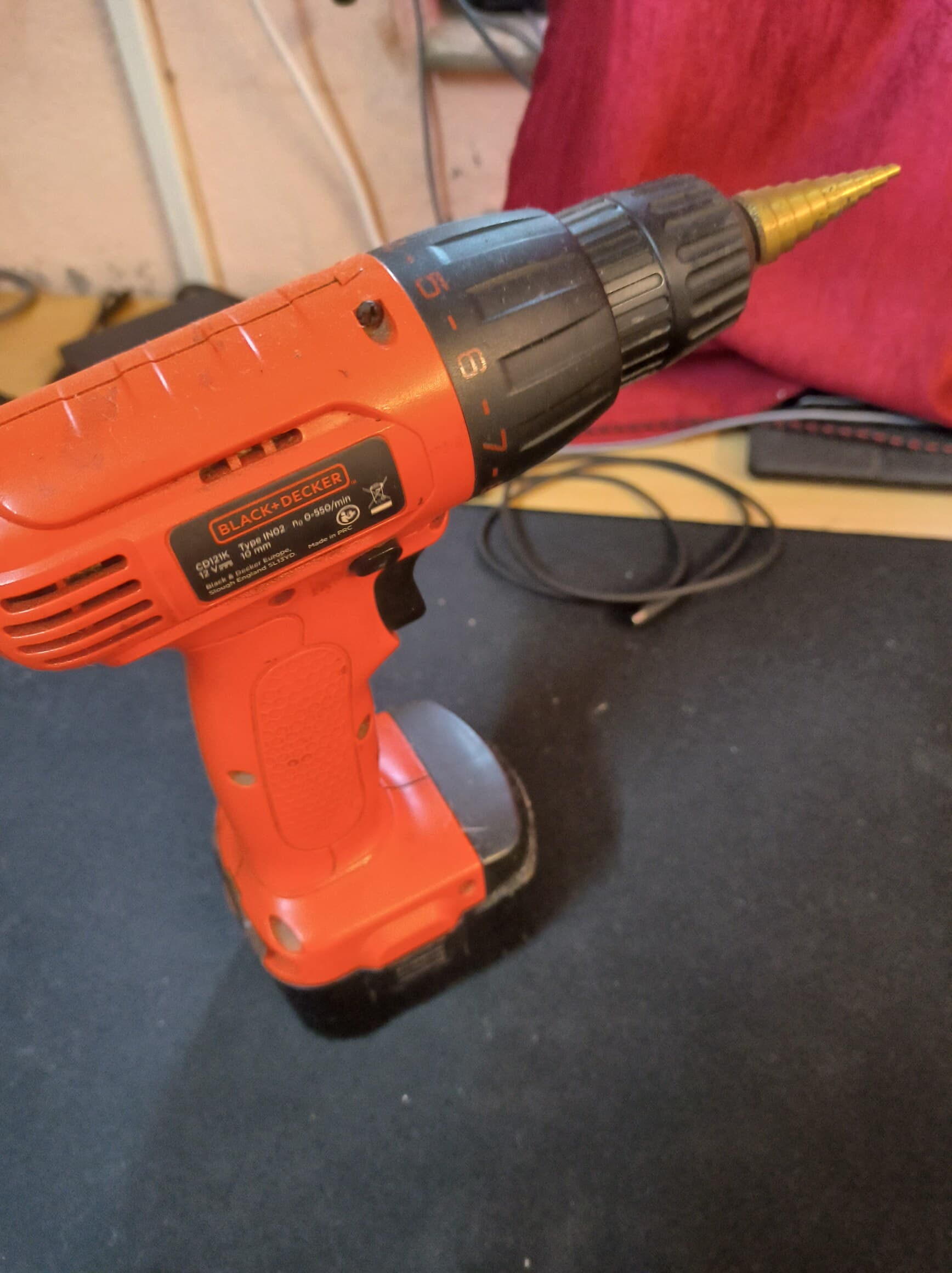
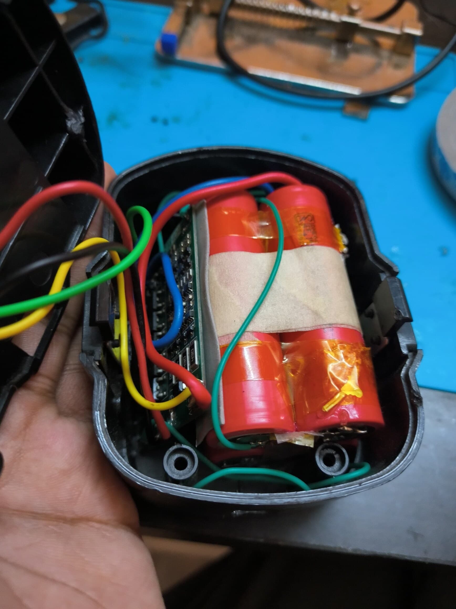
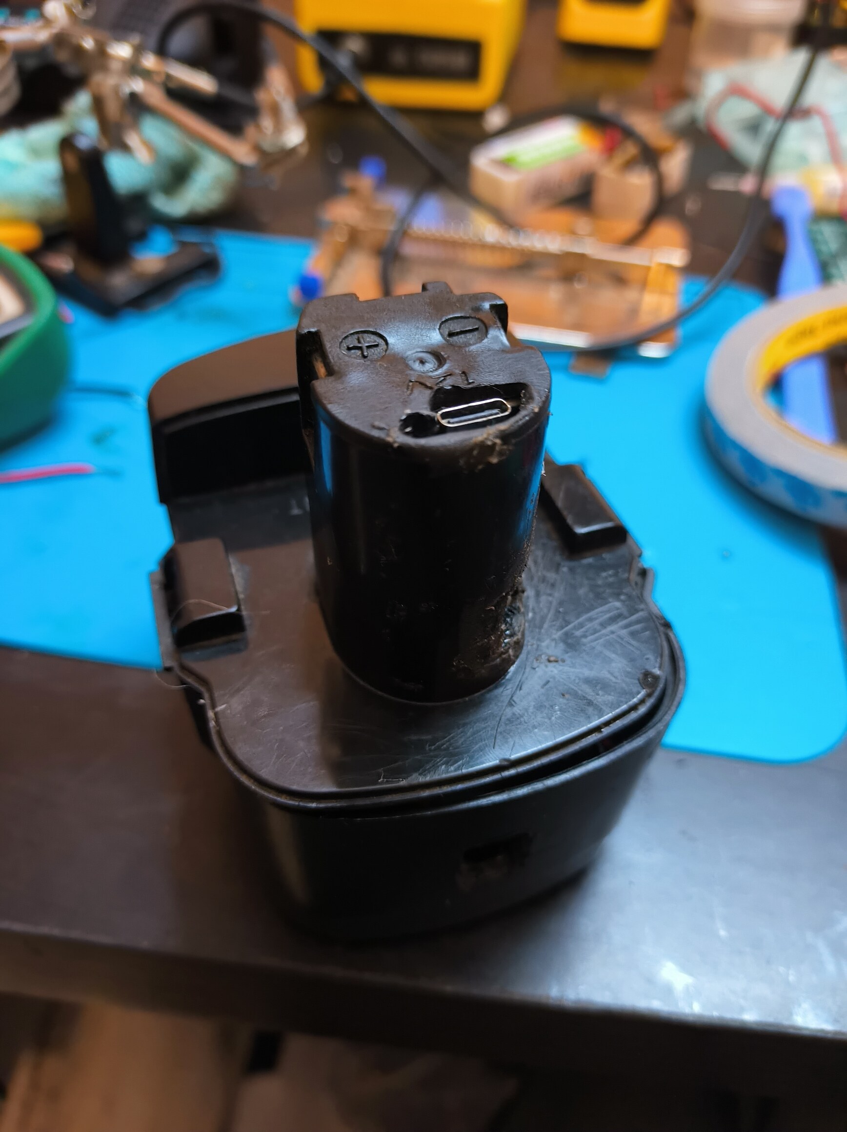
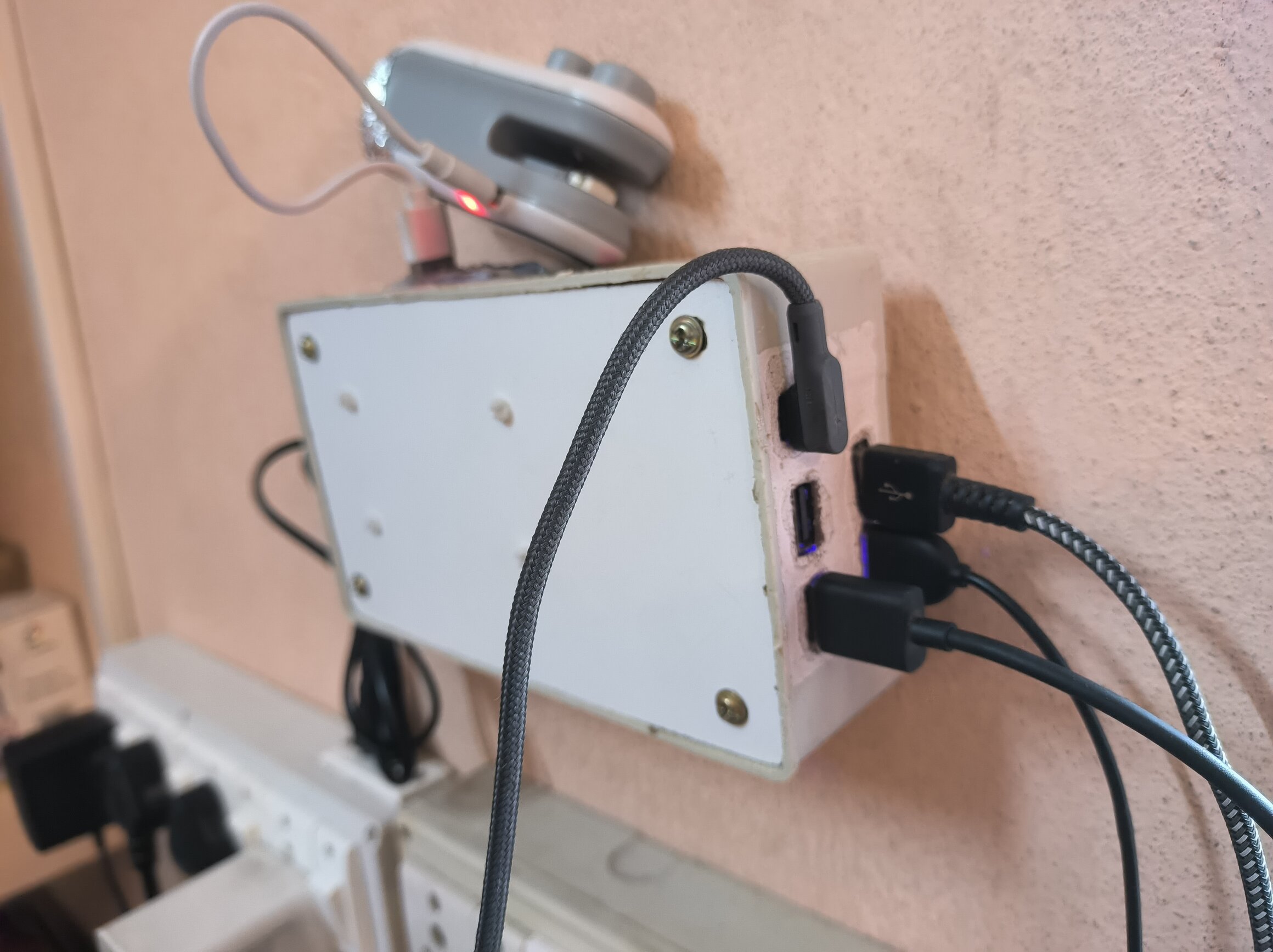
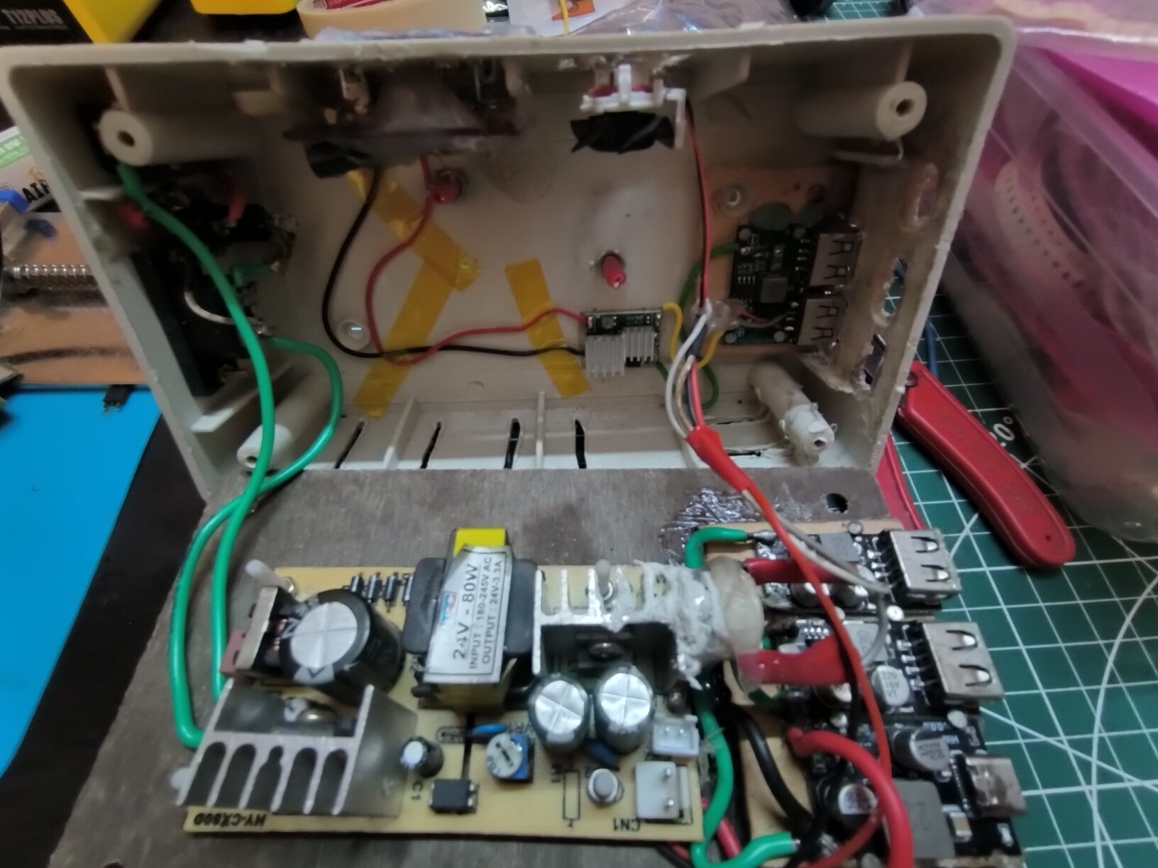
I got this cheapo black and decker cordless drill set long ago and the battery+charger failed rather quick, the battery originally was NiCd based (black and decker loves environment and your health ) and I modded it to lithium cells (some random 18650s) they lasted more than the original cells but something or the other kept failing every now and then, I have remade the whole thing a couple of times now but the shell remained same so it has seen some good amount of abuse. This is the latest iteration with 4x 21700 4500Mah DMEGC cells in 4S config + a BMS + a type c to 4 s charger module.
Some pics:
then I thought wait I need a lot more USBs (even if total capacity is not that much) even if a bit crappy so bodged a buck converter with a circuit board with a few female USB sockets
some miscellaneous stuff like fuse, led indicator, a db8 connector for portability and an automatic fan with a KSD301 thermal switch and a tiny cute fan, a toggle switch etc
All enclosed in a PVC switch box (currently my favorite project boxes just because how easily and relatively cheaply they are available)
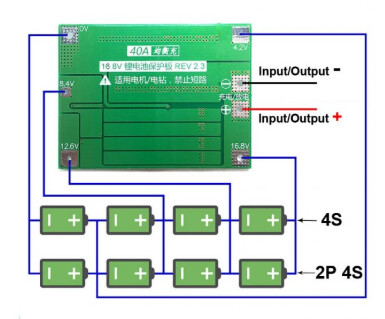
That’s a bit tricky because either way you might face some issues, the thing is that the BMS and charging module both try to manage the high cut off at the end of charging cycle, So
if you attach the charging module to the BMS output, it might oscillate back and forth and the LED indicators might start randomly blinking near full charge condition ( I don’t believe this damages anything but hardly ideal).
I believe the better way is to attach the charging modules directly to the battery terminal across the pack, probably this is the intended way but there is an edge case on some BMS that if the BMS shuts down for whatever reason (protection trigger) it needs a voltage to be applied to turn back on regardless the battery voltage, in that case this strategy might cause hassle
Again, I am not sure and basically doing trial and error to see what works out, I forgot what I have done this time around lol, will need to tear it down to know
EDIT:
not just that but the charging itself too i.e. full charge cut off (and probably CC,CV too?)
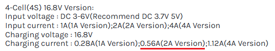
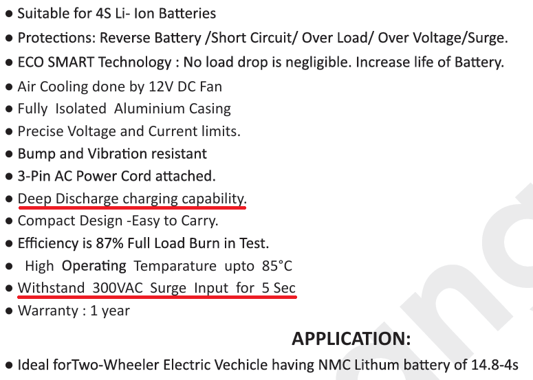
I googled a bit, with 4s battery connected to the BMS it needs exactly 16.2V for charging.
But not just regular 16.2V DC voltage, it needs CV/CC too.
I could be wrong, but I think the charging module you have does not do CV/CC charging it does output CV but switches the frequency to somehow simulate the CV/CC behaviour, with maximum current of 0.56A in your case.
If anyone else reading - this setup does not allow you to power your load and do the charging at the same time. If you do either the charger module or the BMS will go bad.
My room’s shape is such that it’s difficult to control the AC from my bed. Furthermore, the AC is a window unit and sits lower than usual, resulting in it killing the compressor too early even before my room gets cool enough. Either I keep the temp setting too low or use a custom solution… therefore:
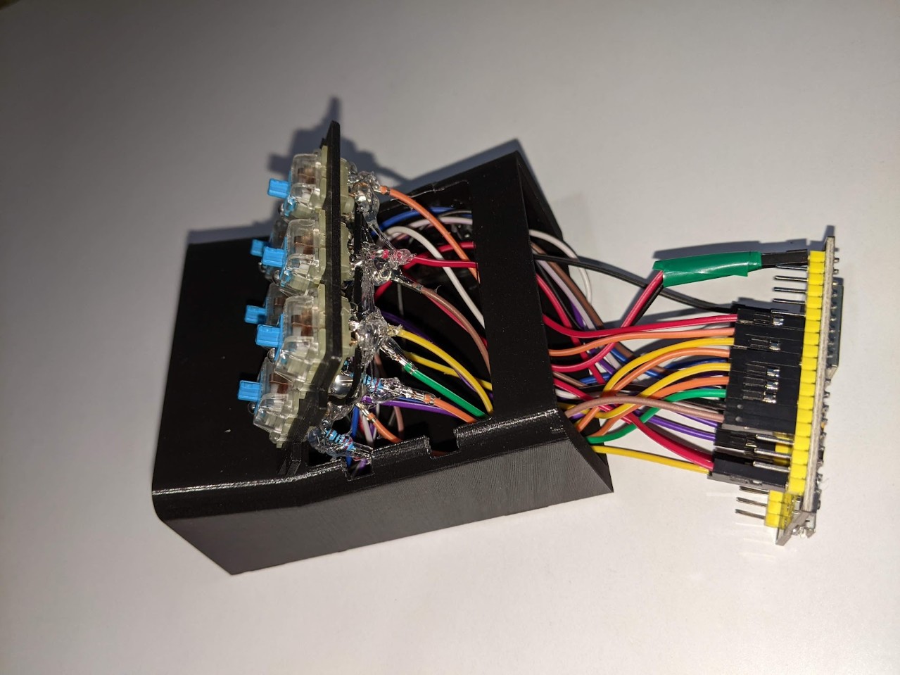
A simple device to control the AC by replicating the remote signal.
Linked to my phone via ESPhome/Home Assistant
Uses an IR Transmitter module, a receiver module (for programming a specific code… kinda unnecessary).
Wemos D1 Mini as the MCU
3D printed case
LEDs for notification (Solid white when AC triggered… blinking when idle, blue led when signal sent)
The activation/deactivation is based on a temperature sensor in another device (see below) that sits on my bedside table.
Not exactly a huge project, but swapping out the firmware in my Mi3 Air purifier with a custom one that links it with Home Assistant and stops all access to Chinese servers. This was a pain to disassemble but worth it.
True. But practically all sources are somewhat current limited and have a higher open voltage, CC/CV isn’t that complicated if the source is weak in terms of total power already and somehow regulates to around given max battery voltage (say 16.8v in this case) when floating. And a typical boost converter would generally be not outputting a lot of current and this particular module does only output max ~0.5A to the 4s battery (the 2A rating is the max USB input current rating).
It is an actual purpose-made IC to do step-up and proper battery charging.
I don’t have any spare similar 4s module but I do have same but in 2s and 3s variants
and they seem to have mainly 2 sop8 ICs:
a step-up battery charging IC CN3302/CN3303/CN3304 (I am guessing the last digit is a number of Series indicator and each IC is made for a specific config)
CN3303 datasheet states:
CN3303 adopts constant
current and quasi-constant voltage(Quasi-CVTM)
mode to charge battery
among other features, this is an actual purpose-made IC and not just some fishy boost converter.
Funnily enough, the option you propose is an objectively worse means of charging but arguably still serviceable, unlike 1s chargers like tp5000, tp4056 etc which offer a plethora of features, you don’t actually need and don’t actually get all those features even in good quality chargers or BMSs, the general consensus for a sane setup is that:
your power supply floats to around max safe battery charge voltage and is current limited (A regular SMPS might trip on voltage drop (i.e. CC stage), might have more current than safe for the battery pack (say 1AH discharged pack getting 10A of current for the SMPS to maintain output voltage or an suboptimal floating voltage)
the battery has a BMS that manages the safety like over discharge, UVP, OVP, temperature, balance etc
the option you suggested (its datasheet) doesn’t state any CC/CV profiles and seems like a regular SMPS with preset suitable voltage and that’s it.
EDIT1:
It’s just for charging stuff, not much more noise than regular SMPS we are already surrounded with I guess.
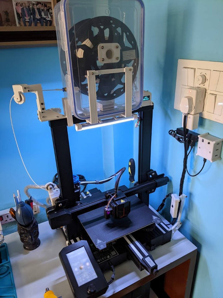
I have to agree with @Heisen 3d printed parts add the charm.
I wish to have one but too expensive for my student ass internship currently, but one day I guess…
till then PVC switch boxes it is.
I liked the idea of using mechanical keyboard switches for these projects! might steal that one for the future
I see, so if I were to automate it via some microcontroller
Could I use some simple relays (say even high current ones like 30A (still easy to find online) for each of green and red and give a pulse for each to trigger on and off?
or are there any special mechanisms I should be aware of?
is 30A rating relay enough?
It is able to detect deep discharge state of the battery, a simple SMPS won’t have that ability. Yes the CN3302/CN3303/CN3304 are purpose made ICs for lithium battery charging, but I personally would trust this one more than the open modules we get in the market. The CV/CC is there I am sure.
The standard TP4056 module does not detect battery “deep discharge state”, which requires reduced charging current for safety. We would know better if the datasheets of CN3302/3/4 were in english.
But whatever the case maybe, at last if your drill works then there is nothing to complain about.
Nothing much to automate unless you want to autostart and shut down . The small cap is permanently wired and the big cap gets connected for a small moment when the power button is pressed .