rsaeon
Patron
Pursuant (corporate speak, ha) to this helpful video:
It became apparent that I needed empirical verification for the connections I would be making in my LiFePO4 projects, unexpected resistances result in heat build-up, and can become disastrous if unchecked — the prismatic cells I'm using are capable of 5C discharge, that's over 500A!
From: https://www.omnicalculator.com/physics/joule-heating
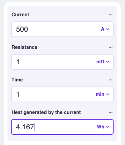
That's (potential) heat generated by a 500A fault over a 1 milli-ohm conductor every minute. Essentially, you would want your conductors to be in the 10's of micro-ohms for safety.
But most commercially available meters look terrible and are priced beyond what I'm able to spend:

So the moment had finally arrived:
And I'm entirely impressed with how intuitive and rewarding the process of building and coding Arduino is! It cannot be stated enough. I'm almost convinced that if we had these technologies back when I was learning about electronics (mid-teenage years in the 90s), we'd be building space stations today. It's just incredible.
Most tutorials have you blink a led as your first Arduino project but I skipped right into making a prototype of this Micro-Ohm Meter and I loved every moment of it!
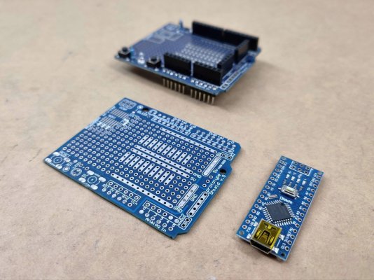
Starting with depopulating a popular prototyping board for Arduino, to serve as the carrier PCB for an Arduino Nano:
Attached headers and a trimpot to adjust contrast for a LCD:
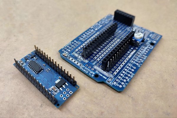
Also seen above is a 0.1uF decoupling capacitor in the bottom left of the proto pcb.
First test with the JHD 8x1 LCD, naturally:
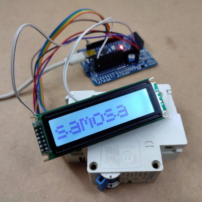
Vollrathd's design incorporated a very cool but tiny OLED — I wanted a larger, easier to read display.
Power is with a 1.2Ah 18650 cell, with a TP4056 module serving as a charger & low voltage disconnect:
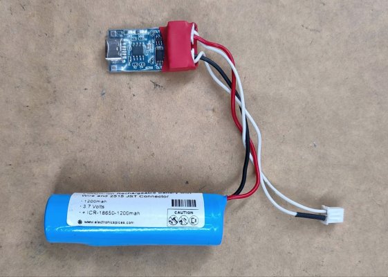
Vollrathd's design has a 2S pack for a higher voltage that'll push >1A through the conductor-under-test. A single cell like this pushes about half that much (through a 5 Ohm power resistor):
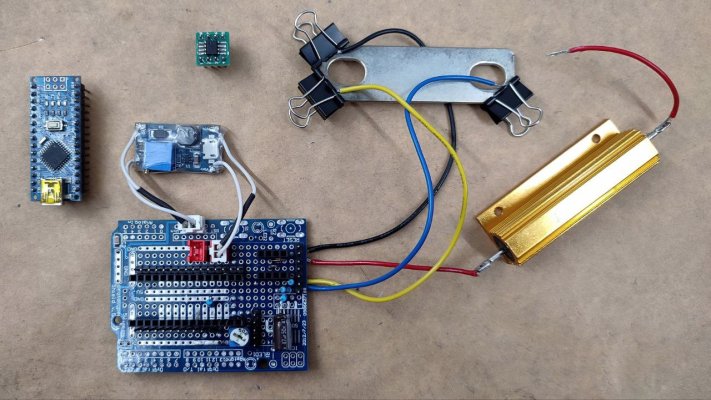
A little boost converter provides 5V for the Arduino and the 18-bit Analogue to Digital Converter, a MCP3422. The other components are two zeners, three resistors and a capacitor for the input protection of the ADC. There are two more resistors arranged as a voltage divider for the Arduino to measure and display the battery voltage (details in a later post).
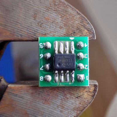
There are only two ways to put this chip on this adapter PCB, so it's not a surprise that I got it wrong (white mark on the top right indicates pin 1, but pin 1 is in the bottom left).
In other news, I seem to have lost my soldering mojo, this is definitely not my best work:
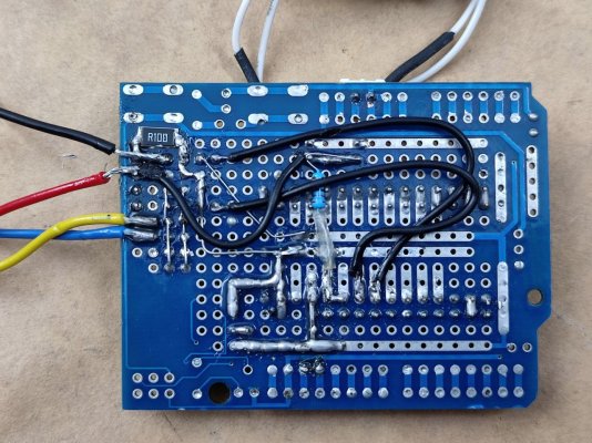
The premise of this meter is that it measures the voltage drop across a known 0.1 Ohm 1% resistor (ideally it should be 0.1%) and derives current through Ohm's law (i = v / r):
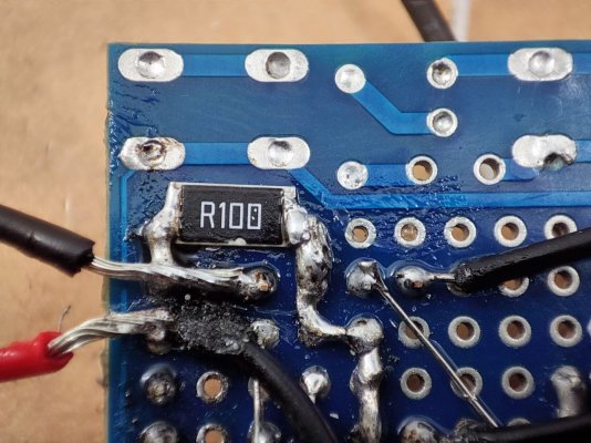
And then it uses that current value, along with the ADC reading of the voltage drop across the conductor-under-test, to derive the resistance of the conductor-under-test.
It's refreshingly simple and clever.
I'm still waiting on the kelvin probes to be delivered (they allow four-terminal sensing: https://en.wikipedia.org/wiki/Four-terminal_sensing) but here's a quick test:
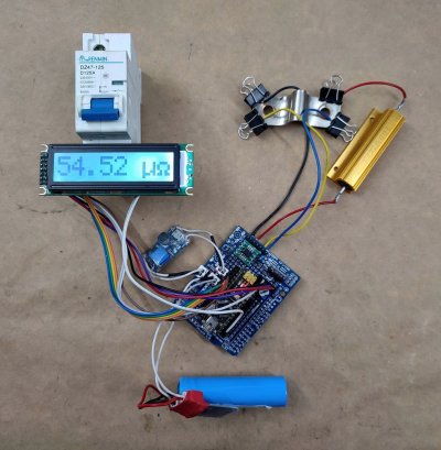
That's 0.05 milli-ohms or ~50 micro-ohms across the bus bar that was installed in the Muscle Grid battery. Cross-sectional area of it would be 20 sq mm (20 x 1mm).
Compare that with this 40 sq mm bus bar (20 x 2mm):
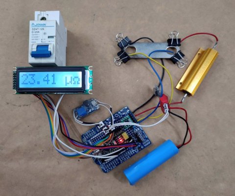
Working as expected, the meter shows about half the resistance at 0.02 milli-ohms or ~20 micro-ohms. Schematic and code to follow.
edit: comparing to the calculated resistance of a somewhat ideal conductor without holes, the uncalibrated reading is within 5 micro-ohms:
https://www.omnicalculator.com/physics/wire-resistance
Vollrathd's original schematic and code are here: https://www.rcgroups.com/forums/showthread.php?3647559-MicroOhmmeter-Project-Revisited/page10
It became apparent that I needed empirical verification for the connections I would be making in my LiFePO4 projects, unexpected resistances result in heat build-up, and can become disastrous if unchecked — the prismatic cells I'm using are capable of 5C discharge, that's over 500A!
From: https://www.omnicalculator.com/physics/joule-heating

That's (potential) heat generated by a 500A fault over a 1 milli-ohm conductor every minute. Essentially, you would want your conductors to be in the 10's of micro-ohms for safety.
But most commercially available meters look terrible and are priced beyond what I'm able to spend:

So the moment had finally arrived:
maybe even finally learn about arduino
And I'm entirely impressed with how intuitive and rewarding the process of building and coding Arduino is! It cannot be stated enough. I'm almost convinced that if we had these technologies back when I was learning about electronics (mid-teenage years in the 90s), we'd be building space stations today. It's just incredible.
Most tutorials have you blink a led as your first Arduino project but I skipped right into making a prototype of this Micro-Ohm Meter and I loved every moment of it!
Starting with depopulating a popular prototyping board for Arduino, to serve as the carrier PCB for an Arduino Nano:

Attached headers and a trimpot to adjust contrast for a LCD:

Also seen above is a 0.1uF decoupling capacitor in the bottom left of the proto pcb.
First test with the JHD 8x1 LCD, naturally:

Vollrathd's design incorporated a very cool but tiny OLED — I wanted a larger, easier to read display.
Power is with a 1.2Ah 18650 cell, with a TP4056 module serving as a charger & low voltage disconnect:

Vollrathd's design has a 2S pack for a higher voltage that'll push >1A through the conductor-under-test. A single cell like this pushes about half that much (through a 5 Ohm power resistor):

A little boost converter provides 5V for the Arduino and the 18-bit Analogue to Digital Converter, a MCP3422. The other components are two zeners, three resistors and a capacitor for the input protection of the ADC. There are two more resistors arranged as a voltage divider for the Arduino to measure and display the battery voltage (details in a later post).

There are only two ways to put this chip on this adapter PCB, so it's not a surprise that I got it wrong (white mark on the top right indicates pin 1, but pin 1 is in the bottom left).
In other news, I seem to have lost my soldering mojo, this is definitely not my best work:

The premise of this meter is that it measures the voltage drop across a known 0.1 Ohm 1% resistor (ideally it should be 0.1%) and derives current through Ohm's law (i = v / r):

And then it uses that current value, along with the ADC reading of the voltage drop across the conductor-under-test, to derive the resistance of the conductor-under-test.
It's refreshingly simple and clever.
I'm still waiting on the kelvin probes to be delivered (they allow four-terminal sensing: https://en.wikipedia.org/wiki/Four-terminal_sensing) but here's a quick test:

That's 0.05 milli-ohms or ~50 micro-ohms across the bus bar that was installed in the Muscle Grid battery. Cross-sectional area of it would be 20 sq mm (20 x 1mm).
Compare that with this 40 sq mm bus bar (20 x 2mm):

Working as expected, the meter shows about half the resistance at 0.02 milli-ohms or ~20 micro-ohms. Schematic and code to follow.
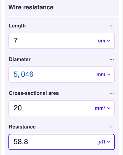
edit: comparing to the calculated resistance of a somewhat ideal conductor without holes, the uncalibrated reading is within 5 micro-ohms:
https://www.omnicalculator.com/physics/wire-resistance

Vollrathd's original schematic and code are here: https://www.rcgroups.com/forums/showthread.php?3647559-MicroOhmmeter-Project-Revisited/page10
Last edited:


