Frozenmetalgear
Disciple
Has anyone tried to use this with a pc?

I actually wanted to use this one into the table, but have no clue to where to start with itYou can use any 2 pin switch you can think of to turn on your PC.
Has anyone tried to use this with a pc?View attachment 176195
Yeah i checked this as well but the only thing that stopped was the other one which be latched into the table while this one should be kept on itI have a similar one I bought from AliExpress a few years back. I'll post a photo of it tomorrow.
In the meantime, Amazon does have something that should work from the desk:
View attachment 176196
Product Link: Desktop Computer Power Switch
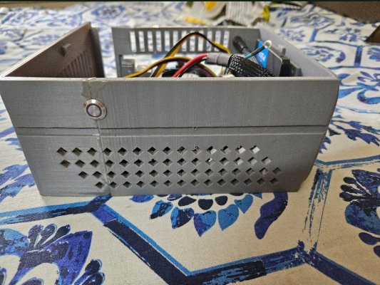
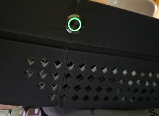
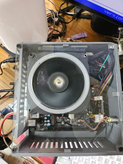
I have used these with a custom 3d printed mini itx case that i built for a router. You want momentary switches and not the latching kind. Also, to power the led, you can connect the other 2 pins to PLED+/- pins on the motherboard.I actually wanted to use this one into the table, but have no clue to where to start with it
This looks neat . I want to do something similar where i can put the switch at the top of the table..I have used these with a custom 3d printed mini itx case that i built for a router. You want momentary switches and not the latching kind. Also, to power the led, you can connect the other 2 pins to PLED+/- pins on the motherboard.
I have the x570 tomahawk. Didn’t knew what to do with the switch’s power requirement. Still need to figure out which goes whereWhat motherboard do you have? There are two pins on it, when they are shorted your PC turns on. You simply connect two pins of this switch to those two pins of your motherboard. The polarity doesn't matter. The switch should be of type non-locking, meaning it should return to open state after every time is de-pressed.
There maybe more wires to the switch, which is used if your button has built in LED.
You can also have multiple switches by connection them in parallel.
Can you link the switch on amazon? I simply used one off robu, https://robu.in/product/green-12-mm-12v-24-v-momentary-metal-switch/ . You can probably get them in different colors. 12V is the max switching voltage rating, led forward voltage is about 2.5V on mine, which goes perfectly with the motherboard PLED pins.This looks neat . I want to do something similar where i can put the switch at the top of the table..
It didn’t knew I could supply it with the pled as it shows that it requires 12v . Also there are more than 4 pins on it i believe
I believe it was this oneCan you link the switch on amazon? I simply used one off robu, https://robu.in/product/green-12-mm-12v-24-v-momentary-metal-switch/ . You can probably get them in different colors. 12V is the max switching voltage rating, led forward voltage is about 2.5V on mine, which goes perfectly with the motherboard PLED pins.
Checked their website, 16mm+ have 5 pins, LED+/-, Common, Normally Open (NO, conducts when pressed) and Normally Close (NC, conducts when not pressed). You'll need to connect the Common and NO pins to your motherboard Power+/- pins, polarity does not matter. They however do not say anything about LED voltage clearly, but it probably is a direct LED connected to the pins. Polarity does matter when connecting LED pins.I believe it was this one
I didn’t had the idea abt the pled at all , can u check this one? I’m trying to use a 19mm one .
Thanks man for checking It out..Checked their website, 16mm+ have 5 pins, LED+/-, Common, Normally Open (NO, conducts when pressed) and Normally Close (NC, conducts when not pressed). You'll need to connect the Common and NO pins to your motherboard Power+/- pins, polarity does not matter. They however do not say anything about LED voltage clearly, but it probably is a direct LED connected to the pins. Polarity does matter when connecting LED pins.
It'd great if you had a digital multimeter, as the diode check mode can tell you the correct polarity as well as the voltage drop (led forward voltage).
I am struggling with this https://techenclave.com/threads/wake-up-by-rtc-alarm-problem.215637/#post-2480398 , maybe you can suggest a solution.You can set the bios to turn on pc automatically when the power source is resumed. So the electric board switch will work as the switch to turn on your pc