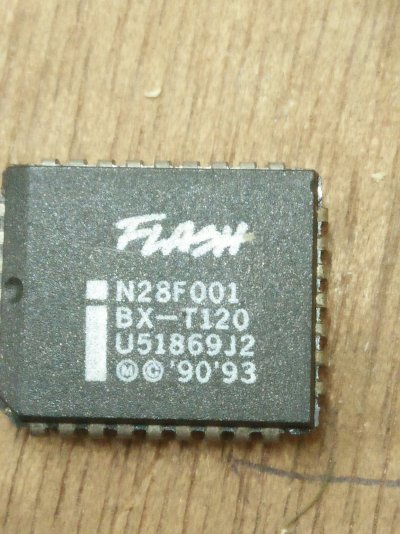
Need Help to program a EEPROM using TL866II Plus Universal Programmer

iosoft

PC enthusiast since MS DOS 5
Skilled
Friends,

If any of you have TL866II Plus Universal Programmer?
I need to program a BIOS file in this IC: N28F001BX-T @PLCC32

If you are from Kolkata, I can visit your place....
If you are outside Kolkata, I can send the ICs to you through Registered Post....

Thanks and regards
 

Attachments

  • IMG20240629135304.jpg
    IMG20240629135304.jpg
    356 KB · Views: 14
If you can't find the programmer, then you could try the following.

I know you have arduino, with arduino mega you can make that your programmer and I think it might program your N28F001BX-T, as per chatGPT. Arduino uno will not work because it doesn't have enough pins.

But first you will have to buy PLCC32 to DIP adapter, which are cheap (currently ₹500 at amazon) and looks something like this.

1719743750354.png


The N28F001BX-T seems to have the following pinout.

1719743905705.png


1719743941346.png


I generated the code from chatGPT for arduino, which looks something like this.

C:
const int addrPins[] = {2, 3, 4, 5, 6, 7, 8, 9, 10, 11, 12, 13, A0, A1, A2, A3, A4}; // Adjust pins as needed, connect to pins A0-A16
const int dataPins[] = {A5, A6, A7, 22, 23, 24, 25, 26}; // Adjust pins as needed, connect to pins DQ0-DQ7

const int CE = 27; // Chip Enable pin
const int OE = 28; // Output Enable pin
const int WE = 29; // Write Enable pin

void setup() {
  for (int i = 0; i < 17; i++) {
    pinMode(addrPins[i], OUTPUT);
  }
 
  for (int i = 0; i < 8; i++) {
    pinMode(dataPins[i], OUTPUT);
  }

  pinMode(CE, OUTPUT);
  pinMode(OE, OUTPUT);
  pinMode(WE, OUTPUT);
 
  digitalWrite(CE, HIGH); // Disable chip initially
  digitalWrite(OE, HIGH);
  digitalWrite(WE, HIGH);
}

void writeByte(unsigned long address, byte data) {
  setAddress(address);
  setData(data);
 
  digitalWrite(CE, LOW); // Enable chip
  digitalWrite(WE, LOW); // Begin write cycle
  delayMicroseconds(1);  // Ensure timing requirements are met
  digitalWrite(WE, HIGH); // End write cycle
  digitalWrite(CE, HIGH); // Disable chip
}

void setAddress(unsigned long address) {
  for (int i = 0; i < 17; i++) {
    digitalWrite(addrPins[i], (address >> i) & 0x01);
  }
}

void setData(byte data) {
  for (int i = 0; i < 8; i++) {
    pinMode(dataPins[i], OUTPUT); // Set pins to output mode
    digitalWrite(dataPins[i], (data >> i) & 0x01);
  }
}

void loop() {
  writeByte(0x00000, 0xAA); // Write data to address 0x00000
  // Add additional write operations as needed
}


Carefully connect the pins over breadboard, also the VPP pin should be connected to 12V for the chip to be in the programming mode. The VCC pin should be connected to 5V. GND pin ground, also connect the 12V ground to 5v ground, very important.

Currently the code only write the byte 0xAA to address 0. You have to convert your bios file into byte array, and put it in the code itself and send data from there to chip, one byte at a time.
 
Last edited:
Back
Top