Clearly the VCC and GND is to be between 2.5 - 4.5v but what exactly are LED+ and LED- , can we drive led strips out of this thing or is it only for small tiny leds
Different settings for T1 and T2 provide various dimming functions:
T1=1, T2=1: Without brightness memory, instant light and dimming with stepless dimming function.
T1=0, T2=1: Without brightness memory, gradual light and dimming with stepless dimming function.
T1=1, T2=0: With brightness memory, gradual light and dimming with stepless dimming function.
T1=0, T2=0: LED three-section touch dimmer function.
The VCC can be 2.5v - 4.5v on VCC and GND pins, on the +- pins I think we are suppose to connect our own mosfet or bjt transistor to control higher power led strip.
Not sure if we put the led directly on the +- pins, then what is the maximum current output, but should be enough for driving a single led or a transistor.
To test use blue or white led, because those have higher forward voltage 3V than all other leds.
Choose VCC 3V. You will be able to test all the 4 modes.
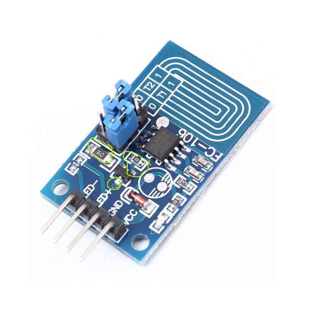
There’s an onboard LED that you can see in the top left which should be indication if no external LED is connected,
The LED+/LED- goes straight to any single LED .
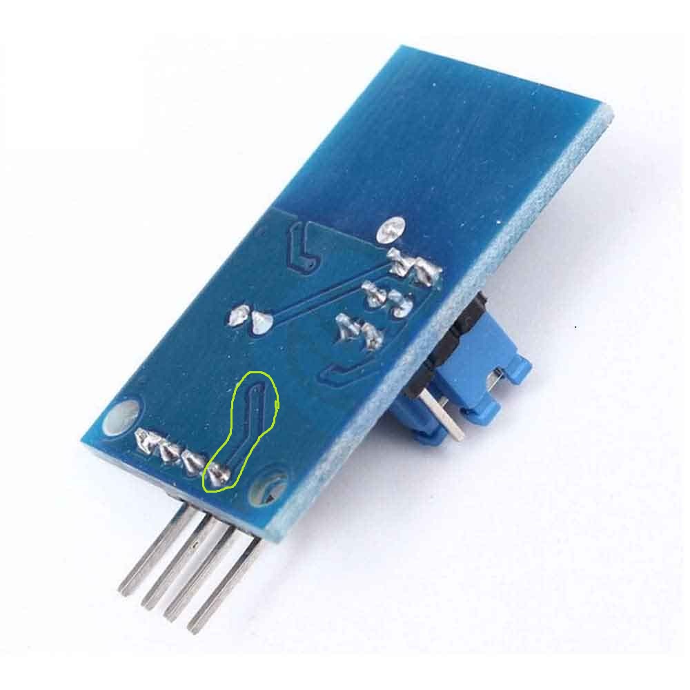
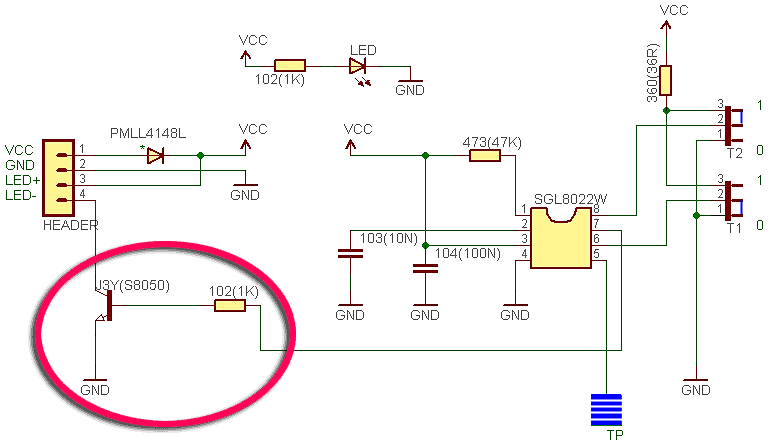
LED- goes to the collector pin (top/middle pin) of the small switching transistor through an PCB trace on the bottom layer. So, it’s a NPN transistor or N-ch mosfet which is driven by the 8 pin controller IC.
LED+ goes to VCC through the 33 Ohm resistor which is essentially a current limting resistor for the LED (large SMD one , with 360 written over it).
The PIN no 1 of the switching transistor connects to the controller IC through a small SMD resistor of 1k-Ohm (with 102 written over it).
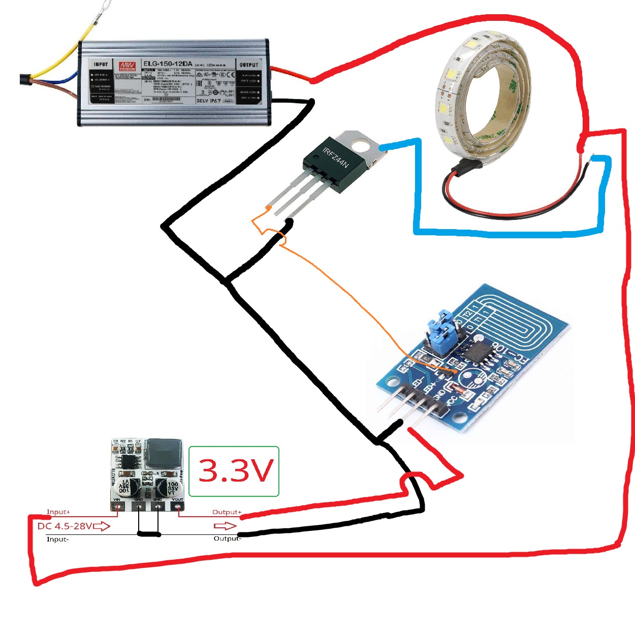
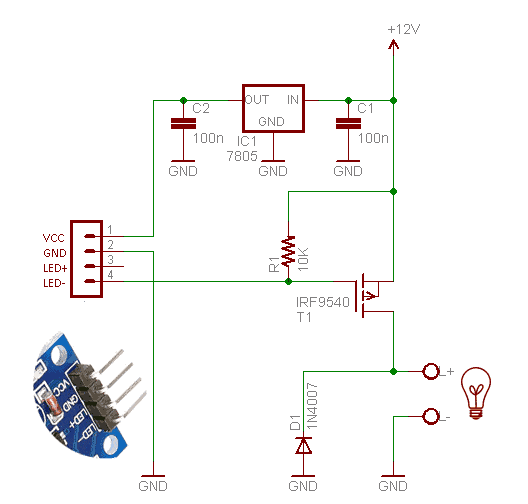
For driving a regular 12v LED strip or other common ones, you’ll need to connect the 12V supply GND to this circuit’s GND if powered separately, or use a 3.3V LDO/regulator/step down to power this board from the same 12V supply which is for the LED strip. Connect +12V directly to the strip. The -ve of the strip goes to a driving MOSFET (n channel) ‘s pin no.2 (drain) and pin no.3 (source)goes to GND or -ve. The pin no. 1 (gate) should be connected to the small mosfet’s pin no 1 at the touch dimmer board. Practically you can use any suitable mosfet , most common ones are IRFZ44N, P55NF05.
There’s an onboard LED that you can see in the top left which should be indication if no external LED is connected,
The LED+/LED- goes straight to any single LED .
LED- goes to the collector pin (top/middle pin) of the small switching transistor through an PCB trace on the bottom layer. So, it’s a NPN transistor or N-ch mosfet which is driven by the 8 pin controller IC.
LED+ goes to VCC through the 33 Ohm resistor which is essentially a current limting resistor for the LED (large SMD one , with 360 written over it).
The PIN no 1 of the switching transistor connects to the controller IC through a small SMD resistor of 1k-Ohm (with 102 written over it).
For driving a regular 12v LED strip or other common ones, you’ll need to connect the 12V supply GND to this circuit’s GND if powered separately, or use a 3.3V LDO/regulator/step down to power this board from the same 12V supply which is for the LED strip. Connect +12V directly to the strip. The -ve of the strip goes to a driving MOSFET (n channel) ‘s pin no.2 (drain) and pin no.3 (source)goes to GND or -ve. The pin no. 1 (gate) should be connected to the small mosfet’s pin no 1 at the touch dimmer board. Practically you can use any suitable mosfet , most common ones are IRFZ44N, P55NF05.
now that is a complex way to use this module, not very sure what real benefit this module gives as compared others. BUt thanks very much Arup, ill try it out
This modules offers smooth On and Off transitions on touch for the led and some other functions like hold to increase brightness and again hold to decrease brightness.
This module is tricky to use.
It seems like the switching is happening on the - pin of the module, we have to connect that to our bjt/mosfet somehow.
Here is the video with full connections (sadly in another language) use subtitles, how to connect it with external mosfet.
I am interested in this module, will buy soon and post schematic.
This is the circuit that is needed to drive a 12V LED strip from this module. We have to use a P channel Mosfet or PNP transistor. The parts are cheap.