Regarding cost, the length of the cable changes the final cost. As more wire it uses the higher the cost will be. So if you can dm me your length requirement I can give you a accurate answer.
Also MSI seems to be acting cheap by withholding the pin-out diagram that they actually released Link
Since you are using finolex or polycab wires , do they manufacture tinned wires or normal copper wires ? If it is the household copper wires a word of caution . Copper corrodes when exposed to air and over a period of time the current capability of the wire reduces .
While ferrules are good for crimping , they do not help in transfer the current as such . Solder is the better and reliable option
Most issues arise from the pin connector . Not much of quality pins around . Especially the “spring” action of the pin weakens with a few connections and disconnections .
I was looking for additional sata cables for my PSU for a while and @b.life made these for me. Such a gem of a guy and so helpful. Helped me understand how the cables work and also shared tons of material to try and test out and modify cables on my own. I installed both of these in my system last week (These replaced the molex to sata adapters i was using and also let me add new hdds) and they have been working flawlessly.
Best interaction I have had on TE so far and I loved meeting someone so passionate about his hobby and helping fellow members.
Regarding your doubts, let me break it into sections so it is easy to answer,
Regarding Wire size and Standards
I never use polycab as they use less copper for any given gauge. It is either Finolex or Gloster only.
Regarding wire thickness, the inner diameter is almost universal(see point 1 for exception), but the outer diameter changes depending on the insulation thickness used.
When it says XX.XXsqmm, this is a universal standard with IEC specifications Website. The specification clearly defines the inner and outer diameter(Point 2 above) but most of the manufactures here in India don’t think much of it. From my experience only Gloster and Finolex does stick to standards. Maybe there are others but I have not found one.
Regarding Copper and Wire Exposure
There are only 2 types of wires used in electrical works. Copper and Aluminum and copper is the best conductor of electricity except gold, So I am not sure what you mean by normal copper wire.
I didn’t actually understand the part about wire getting exposed to air part so I don’t know what to say in that regard. But one thing I can say is nowhere the wire is actually exposed to air where there is a chance of it corroding. Maybe can you expand on that so I can clear your doubts.
Regarding Crimping & Soldering
Crimping is used because it provides a strong and reliable connection and also without the heat damage to the plastic shielding that is caused due to soldering.
When we solder the joint, the solder will flow back into the wire underneath the plastic and make it brittle not only the joints but also the nearby areas which make it impossible to bend or in our case route the cable.
A crimped joint can be bent once, it wont break or damage the wire and it will stay as such but a solder joint will break.
The resistance difference between the crimped and soldered joint is so low that it doesn’t actually matters in any applications.
I don’t know where you get the idea that crimping wont help in transfer of current but I will link to a NASA standard procedure document that defines how connections should be made. I hope this help in clearing out your doubts.
Regarding Terminal Pins and Terminal Pin Types.
ATX standard defines the mating count, pin material and its type and these have been as there for as long as ATX has been around. I can say for sure that none of the connectors or pins are made for infinite mating cycles. If my memory is correct the latest 12VHPWR is rated for 30 mating cycles I believe, so if used beyond that then it will have mechanical defects and leads to electrical issues, will it fail on 31? I am not sure but it is the standard so anything after 30 is a bonus. It is the same with every connector and pins in the ATX specification.
Another problem is using pins beyond its designated capacity. A normal pin used in PCI-E connector is designed for about 9A(it can handle about 10-11A) but when you draw more than that it will get hot and melt the plastic connector. This is not the problem with the pins but the uneven power draw of the application, in recent times the famous Nvidia 4xxx and 5xxx GPU’s are the prime example.
About 4 post above your post I have posted picture of mechanically damaged pins. How it happened I have no idea even the user didn’t know. Is the pin of lesser quality? no
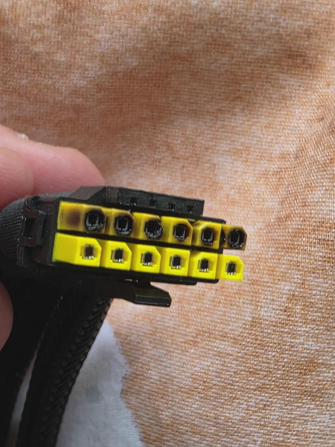
About 5 posts above your post I have posted pictures of pins damaged due to heat. This is a unique case, the outer plastic is fine no symptoms there but the pins have heat damage. Checking the cable it is a OEM made cable from Corsair I think(not sure) so they didn’t skimp on material but somehow the pins got hot due to over current draw.
In these two cases one has mechanical damage due to mishandling and another due to improper power draw. In both cases the pins are not the issue it is either the end user or the application.
I hope I have answered your doubts, if I missed any let me know.
When you crimp bare copper wire there is always a change that copper can react and turn into copper oxide , lowering conductivity .
If you happen to cut open wiring harness , you will find wires are in silver colour and not copper colour . Those wires are pre-tinned .
When you use tinned copper wire soldering is faster since it already tinned and does not damage the insulation .
I never meant to say crimps do not transfer current . Even with the NASA document that you shared there is also a chapter on solder joints . The document is more to deal with industrial wiring . A bad crimp can look good , but might be inadequate .
I would rather say it is uneven mating surface of the pins with the connector resulting in heat . A tight pin and connector will help transfer much more amps than an improper connector .
All the above points of mine are small incremental improvements of what you are excellently doing .
May be some day you will start a business full time and we can find branded cables .
I don’t know how you quoted the post but for the life of me I don’t know how to do it with this editor so it’s jumbled reply from me, sorry about that.
Every wire is actually crimped, be it MB,EPS,PCIe either by manufacturer(PSU Makers) or custom cable makers because there is no place where the bare copper is actually exposed to the elements. I tried to follow a wire and still didn’t see it. Am I missing the forest for the tree here?
Even if such oxidization is to happen where in the electrical properties of the wire is affected, I am pretty sure by that time the psu would have long gone to landfill. If you have some free time please dig into the yacht or boat owners forums, there this tinned wire vs bare copper wire debate has been going on for a long time and the general opinion is an end covered copper wire is more than enough but if you have more money then go ahead with tinned wires.
One of the reasons why I linked to NASA standard document is, that standard is used when making cables for their rockets/satellites/etc. And If they say a crimped connection is good enough then I am sure it is good enough for everyone else.
As you said “While ferrules are good for crimping , they do not help in transfer the current as such” I thought you meant the crimp method is not up to standard.
Regarding the Power draw/melting connector thing if you get time watch this video about the 50xx series circuit analysis, that video is about an hour long and kinda goes into depth, anyway I digress this is not what we are talking about.
The chance of having a improper connection due to bent pins is very low when dealing with molex, sata, PCI-e pins(12VHPWR is a different story). In these cables almost 99.9% of the time the power issue(and resulting heat) is due to overload. I myself have provided an example of a bent pin few post above but that is an outlier as far as I know. From what I have seen/heard/read the pins are generally sold unless someone pokes it with something other than the intended connector, but when that happens no matter the quality of the connector it will get damaged. So I kinda believe we are safe in that regard.
Said all that, the ATX pins are almost standard with split in the middle and a long dimple on both sides. It has been as such for a long time and they have worked till date, so I am not sure what can be changed, I will ask my supplier if they have any updated model though.
All feedback are always welcome, I don’t know everything so I am more than happy to learn from others.
You are the 10+ person who talked about me starting a business but with my photo skills and marketing I will be wounder if I sell more than one lol
Crimp is fine . If you are splitting the wires then a solder or a crimp and then solder is good .
No. Even if the wire is covered the copper can still oxidise inside the insulation if there are air gaps . I do agree that the PSU would have died its natural death before than happens . At the same time , spending so much of time and effort on cables , I just like it 100% perfect . A cpu cabinet can get very humid due to heat and fans inside , so being extra cautious .
What I meant was that the crimp holds the 2 wires together . The current transfer is between the wires and on the outer skin of the copper wire . So a ferrule just holds the wires together if the wires are twisted before crimping .
I have had quite a few failure experience with molex and sata connectors . Many a times I have cut the molex or sata power and rewired . May be the ones on some PSU that you use have not caused any issues , but I always felt that the material thickness of the socket pins is a problem for tighter clamp force on the pins
May be much more thicker gauge .
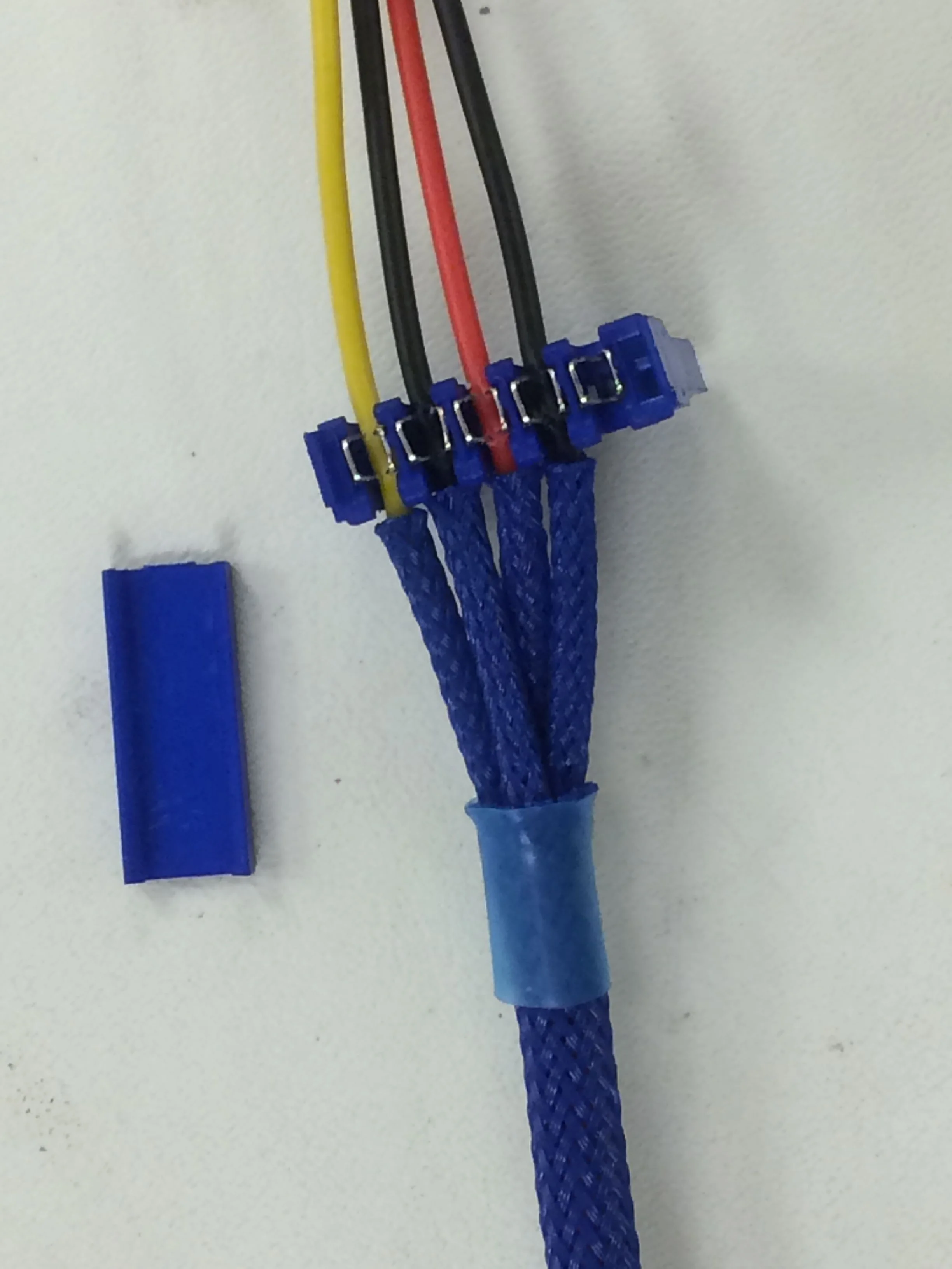
Yes , No patience especially given that the guy is tracing the circuit and trying to explain . I would still say the burnt out connectors are due to the loose connection resulting in heat rather than the overload . Here is an example of the positive pin getting burnt while the negative pins are fine .
I referenced a NASA standard that said crimp is good enough but you keep saying only soldering is good, unless you can reference a international standard/practice where their requirement is more stringent than what NASA needs, that says soldering is better than crimp, this discussion is not going anywhere.
“I just like it 100% perfect” by this logic even the tinned wire is not good enough as the ends of these wires are exposed copper and will oxidize and it will spread. The wires(non tinned copper) are going to last longer than the psu for which it was made, in which case what seem to be the issue here? There has been millions of psu made till date and not one psu wire failed due to corrosion of its wire. So unless there is a published study that states otherwise there is nothing more to discuss as this looks like trying to find a problem when none exist.
The thickness of the plate that is used in the manufacturing the pins are defined in standard, it cannot be increased nor decreased. If certain manufactures doesn’t follow then it is on them. But a pin with standard specification provides enough pressure for good contact that is all that I can say. If you are interested you can search for surface contact area vs current transfer capacity studies.
I hope you do understand that a loose connection will make the the connection overload and that leads to heating? A loose connection that can handle 1A load will never overheat if all it draws is 1A but the moment you pull in 2A it will overheat. Like I said in the above point, please search for surface contact area vs current transfer capacity studies for better understanding on this subject.
You did mention NASA standard , but I am not able to locate any information on crimps or ferrule standards from page 58 . All I could find is general talk on how to crimp and the tool settings .
The same NASA document explains in details on soldering , ferrule and the methods of soldering .
All that I said was for breakout cables Solder is much more fool proof for optimal conductivity which the NASA document also says .
If that is the case , why would PSU manufacturers use more expensive tinned cables rather than use bare metal copper wires ? If you happen to strip even the cheapest of PSU , you will find tinned wires . The sata connector is connected to the wires by punching the connectors into the wires and obviously no one wants a break down at that point .
Not really . Connector pin thickness varies with different manufacturers and so does the metal quality .
Yes and that is what I have been saying . You can also check posts on power strips and home diy thread where I have said the same .
It is not about the capacity . It is about the intermittent draw and resistance arcing which occurs when the connection is loose .
You claim that soldering is better than crimping, so show a document that says soldering is better than crimping, NASA document doesn’t says so. Unless you can prove that with evidence, this discussion is useless.
Then ask the psu manufactures why and reference that here, unless you show proof of your claim with either independent study or with OEM reports, it has no value. It is not my job to prove or disprove your opinions. You are creating a problem where none exist.
I said it before and I say it again, The standards are there if someone doesn’t follow it then it is on them.
You seem to not understand the surface contact area vs current transfer capacity issue. I tried to point you in the correct direction but you seem to have some other ideas. Anyways this issue has nothing to do with me or this thread, so I am going to stop responding to that.
If you have proof for your claims then post them and I am more than happy to discuss, else I don’t think you are adding anything of value here.
That is called Industry standard . IEC 62368-1:2023 . Why are processors gold plated ? To prevent the pins or pads from corrosion . If the argument is going to be , why would the processor pins corrode in a cabinet inside a house or office when not under a water fall , no one would be able to provide an answer to your argument .
You seem to think I am not so intelligent to understand something as simple as bigger the wire size , higher the current transfer .
I love this back and forth even though I don’t agree with either of you, but it is very informative and entertaining.
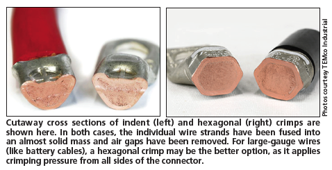
Have either of you not witnessed what’s called a cold weld during crimping? It’s the reason why hydraulic crimpers exist. Basically, you exert enough force on the stranded copper bits (tinned or bare) that they compress into essentially what is a solid chunk of copper, driving out all air and preventing any future oxidation/corrosion. This is then sealed off with heat shrink that has an internal heat-activated adhesive (called marine grade heat shrink, I haven’t been able to find it in India though some people just use regular glue on the ends as a compromise).
The link goes on to explain how using solder as a filler in joints lowers electrical conductivity, which is why I avoid it as a primary solution for wire to connector scenarios unless if the connector enforces the use of solder, like in audio connectors or dc power jacks.
There is a use case for solder, such as wire to wire joints after a lineman’s splice like in the NASA document (where the wires are twisted tightly and then solder is used as protective layer) and component to pcb joints (where solder is used minimally and the joint is fixed in space).
Solder usually works out when there’s little if any physical or vibrational interference such as switch boxes and mcbs. But the inside of a computer case will see constant vibrations from its internal fans, and a soldered wire to pin connection will eventually crack and fail because pc connectors have no strain relief. Wire-to-wire connections will be fine for the most part.
The lowered conductivity of solder also has minimal effect at low current (like 230V switches that see maybe 100W) but it would be problematic at high current (like a 12V graphics card that pulls 400W)
Solder vs crimp has become an endless, revolving discussion in every electrical community in recent years as the old-timers staunchly support solder and the new kids raise slogans for crimps. It’s always fun.
Yes , I am aware and those hydraulic crimpers are not cheap . They cost in lakhs to do a crimp like the one in the picture .
If the crimp is not crimped properly , no tools for measuring the crimped area , tensile strength is not measurable how does one depend on the crimp ? I was not talking about any connector crimping . I was talking about soldering wires branched off .
Computer case fan vibrations are negligible compared to an aircraft or automotive usage where vibrations and stress play an important role . Inside the SMPS the wires are soldered to the board and never seen a break down except for dry solder joints after a decade .
There are 3 voltages . 12v , 5v and 3.3 v . The 5v and 3.3v carry substantial current as well .
Addendum: ferrules are for safety above everything else, so that you don’t accidentally get electrocuted and to prevent loose strands from arcing. They’re convenient, but not superior.
Also: from the link, criticism of crimps is usually because of bad crimps (ha):
Cheap crimping pliers and throwaway crimping supplies are probably responsible for giving crimped electrical connections a bad reputation with many techs. The right crimping tool should grip the crimp connector, then compress it in a controlled fashion that fuses the wires into a solid mass. The wrong crimping tool may smash the connector instead, possibly damaging the crimped wire in the process and setting things up for a repeat failure.
That is what I have been saying on the DIY thread as well .
The cheaper 20-100 amp crimp tools do not have enough torque to tighten to specs . When there are air gaps in the crimp the oxidation can lead to catastrophic failures .
Cables inside the smps often have some kind of strain-relief.
I have a manual hydraulic crimp tool, I have gotten cold welds with it down to 4sq mm, it’s really awesome. It was around 4000, which makes it the most expensive “hand” tool that I own:
There’s probably a reason why PSU manufacturers use tinned wire with crimped connections.
I think in their cost/reliability analysis, they decided that the convenience/speed of crimping is preferred within the time frame of their warranty, or lifespan of the unit, around 10 or 12 years.
And this makes sense, I asked an urban clap electrician about why urban clap has a service to replace internal wiring within walls (I assumed they were permanent), he said it becomes necessary after a couple of decades. I’m assuming this is the time frame for the insulation to disintegrate and the copper to become corroded/oxidized.
Because of the above . The wires are punched and not crimped or soldered . Humidity can corrode and the contact may get compromised . Many PSU have molded connectors which is fine for normal wire .
That is not just the copper . The heat ,humidity can corrode the insulation . Cheap insulation material can be “ porous “ and cause the copper to oxidise
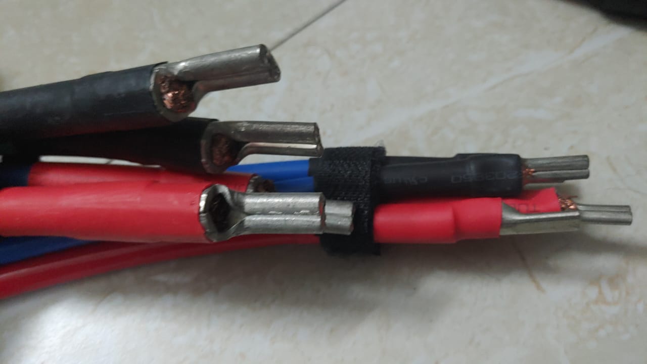
@rsaeon Yes I am aware of cold weld crimping, in-fact the first job that I ever did on TE was for @Mann , where in wires of size 35sqmm and 16sqmm where used. The requirement was for 220A(or 250A I am not sure now) of power delivery so I decided that’s the best option. Link to the job photos.
Regarding crimping, I have proven my point of “If it is good enough for NASA then it is good enough for me” and you have yet to link even a single published standard document or study to support your claims stating otherwise.
Regarding copper corroding, Your claim of copper corroding and leading to issues is like saying sun is going to go supernova and asking us to take action. I have been saying from the beginning that even if corrosion is to happen, the psu would have long gone to landfill by the time that corrosion has any effect. So I will ask again provide proof of wire failure in psu due to copper corrosion.
I don’t like to delete posts/replies in a for sale thread, as it gives readers context but I don’t like unsubstantiated claims and fearmongering here. So provide proof for your claims or say you don’t have one and that it is your personal opinion and move on.
Those copper lugs are tinned . Why ? They are meant to be crimped and soldered . The tinning is also done to prevent corrosion .
I have given a link to a battery manufacturer who has tested the crimped and crimp soldered terminals . Please check .
I have also give you the International industry standard for the manufacture of SMPS and PSU in computers , laptops . Please go through it . That IEC standard is what is used to approve in BIS in India .
I do not have proof , but I have had quite a few instances of Sata power socket or Molex connector failing due to wires or the pins .
If it is good enough for NASA it does not mean it would be good for any application . NASA will typically over engineer the conductor , core , crimps , insulation and they will do a million tests before approving even a fuse wire . They will also have built in redundancies into the systems .
When I went for a job the first time , the company director asked me to define what is “ Quality “ .
I said the best is quality .
Then he asked me I will give you the worlds best and the costliest fountain pen of the highest quality and a 1 re ball pen . Which would you choose to make a carbon copy ?
I told him I would choose the ball pen . Then he explained quality and standards are relative .
So similar is the NASA standard vs Industry standard .
Neways , I do not want to derail your business thread . I am not posting anymore on this .