PART 1: THE SENSOR
We need this sensor to read the water level inside the tank. For this we’ll be using the US-100 Ultrasonic Distance Sensor module. This sensor is 3.3V logic compatible and has a UART mode where it returns a distance reading that takes into account the current temperature for better accuracy. This sensor is wired to a ESP8266 module which is flashed with Tasmota and powered by POE. More info on the software bits after the photos.
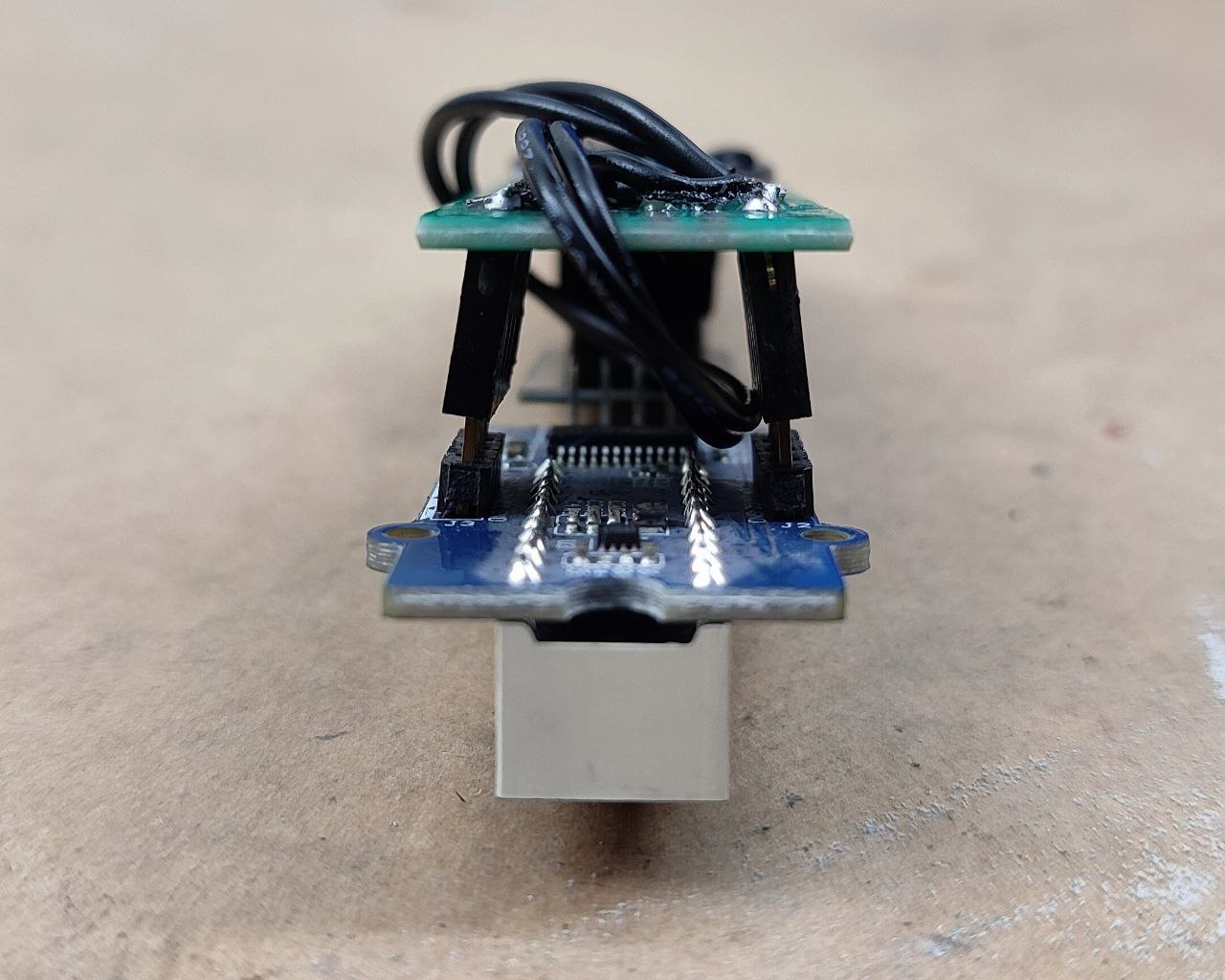
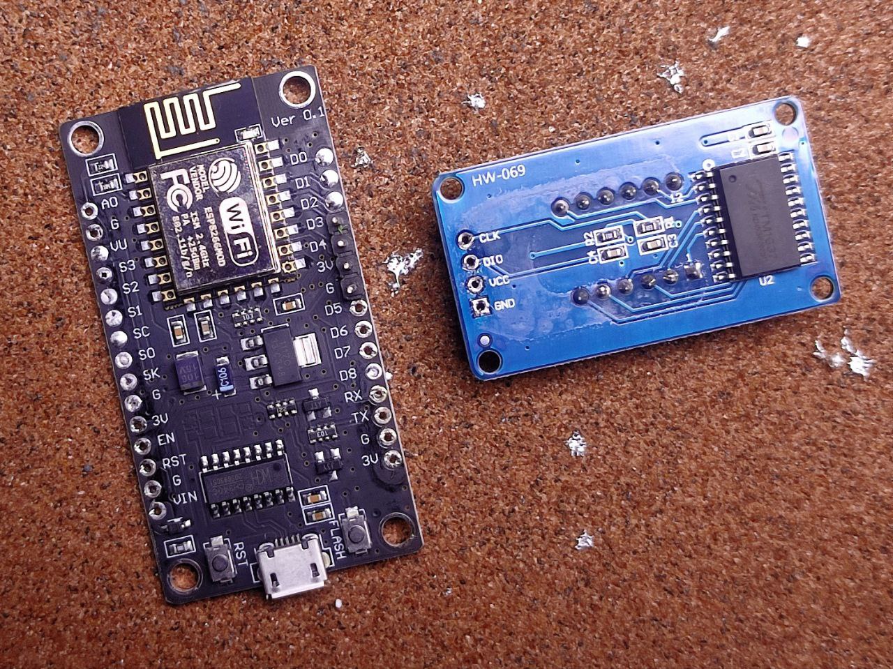
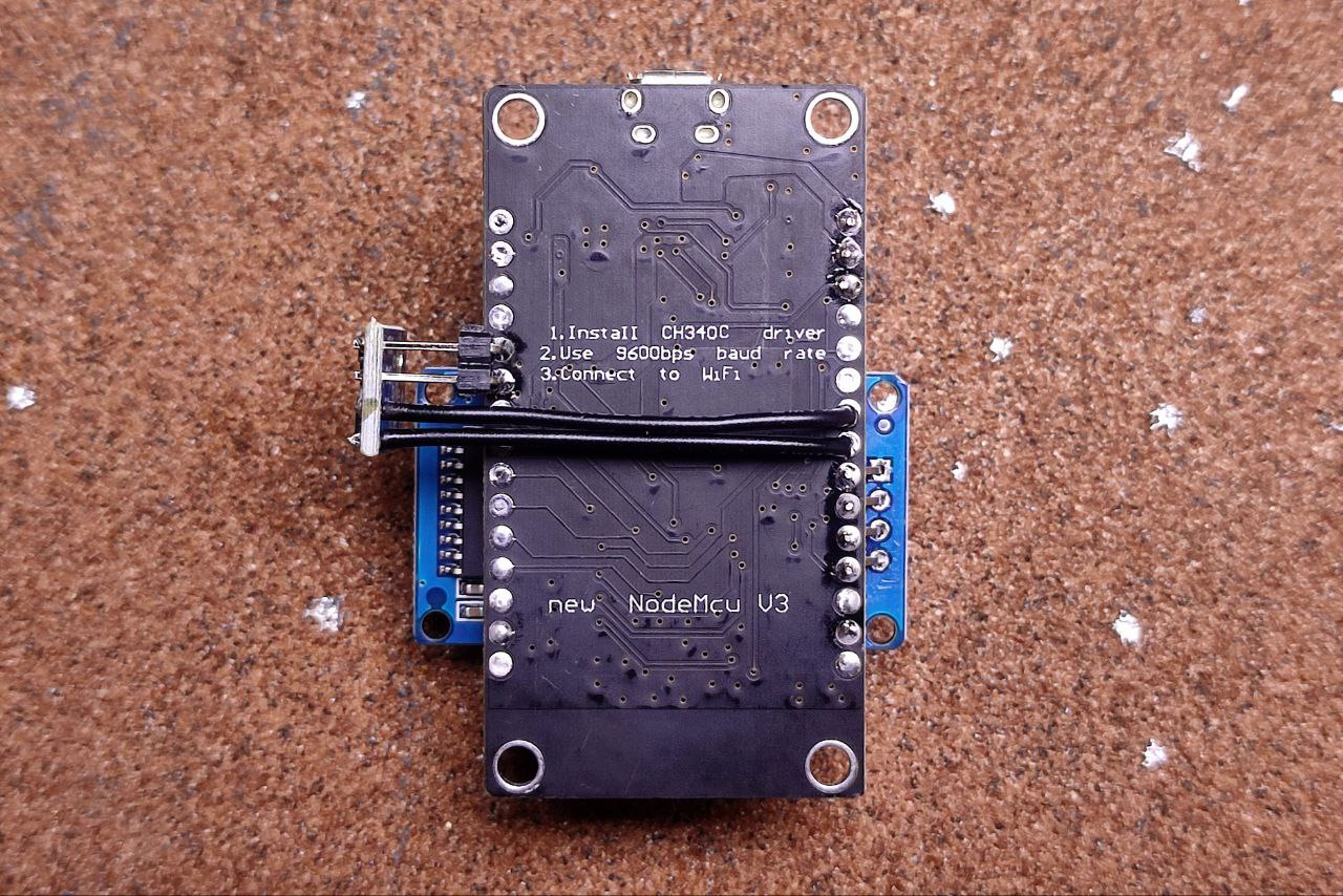
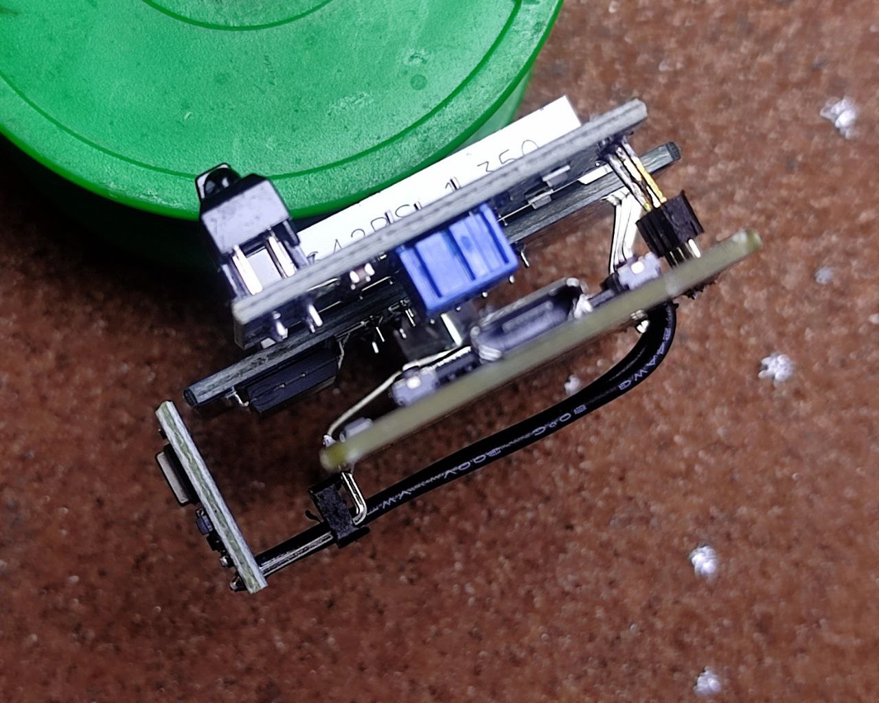
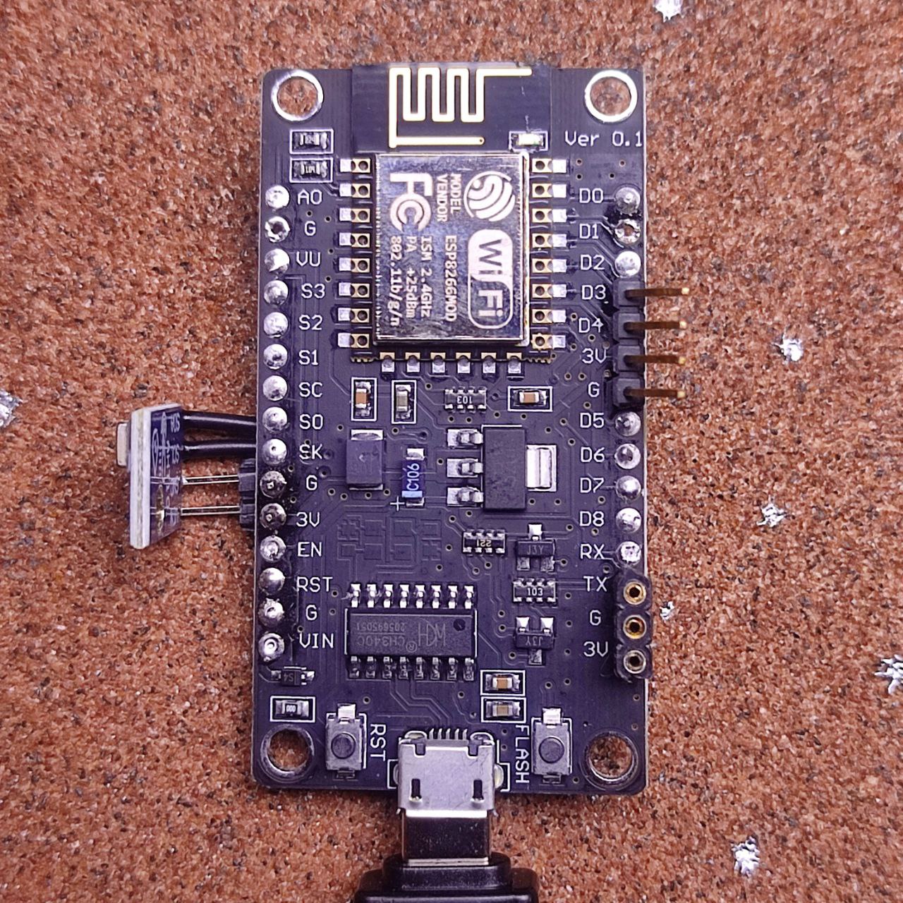
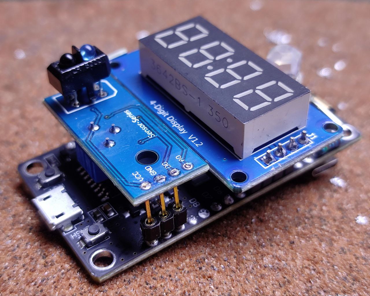
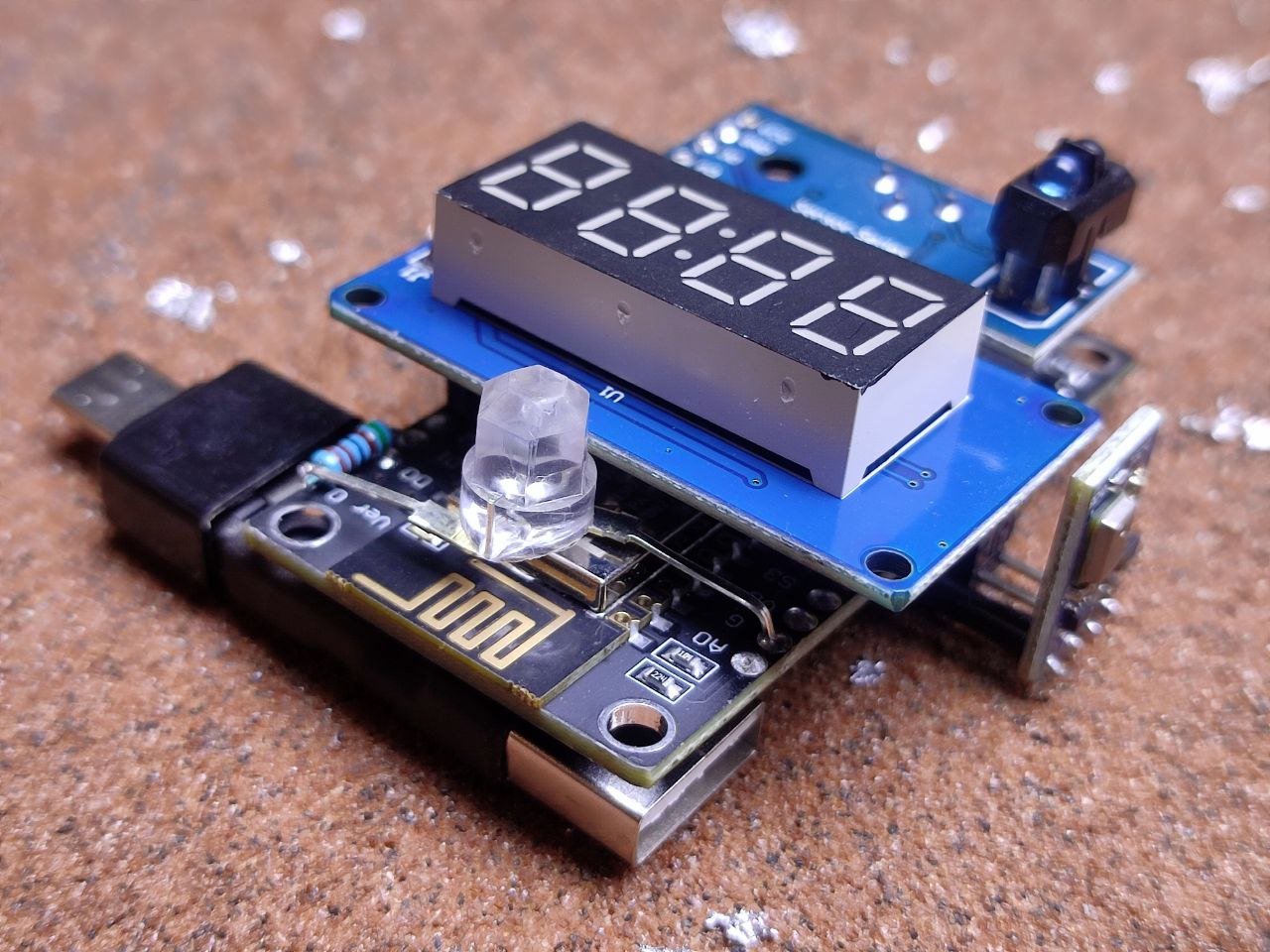
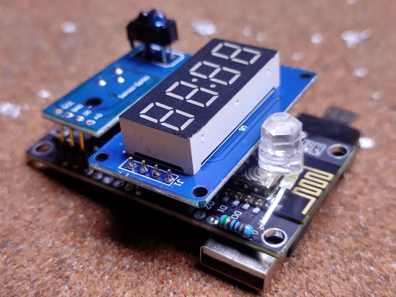
Here is the hardware:
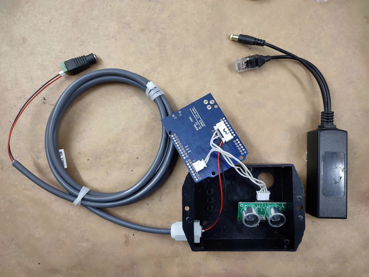
That’s a WEMOS D1 R2 with the US-100 wired. Power is fed in through a 2M length of outdoor-rated CCTV cable that will be plugged into a 12V POE splitter. This WEMOS board can handle 12V input safely but you can use any ESP8266 board with a voltage converter module. I’ve removed all of the pins and DC input on this WEMOS board to make it easier to install.
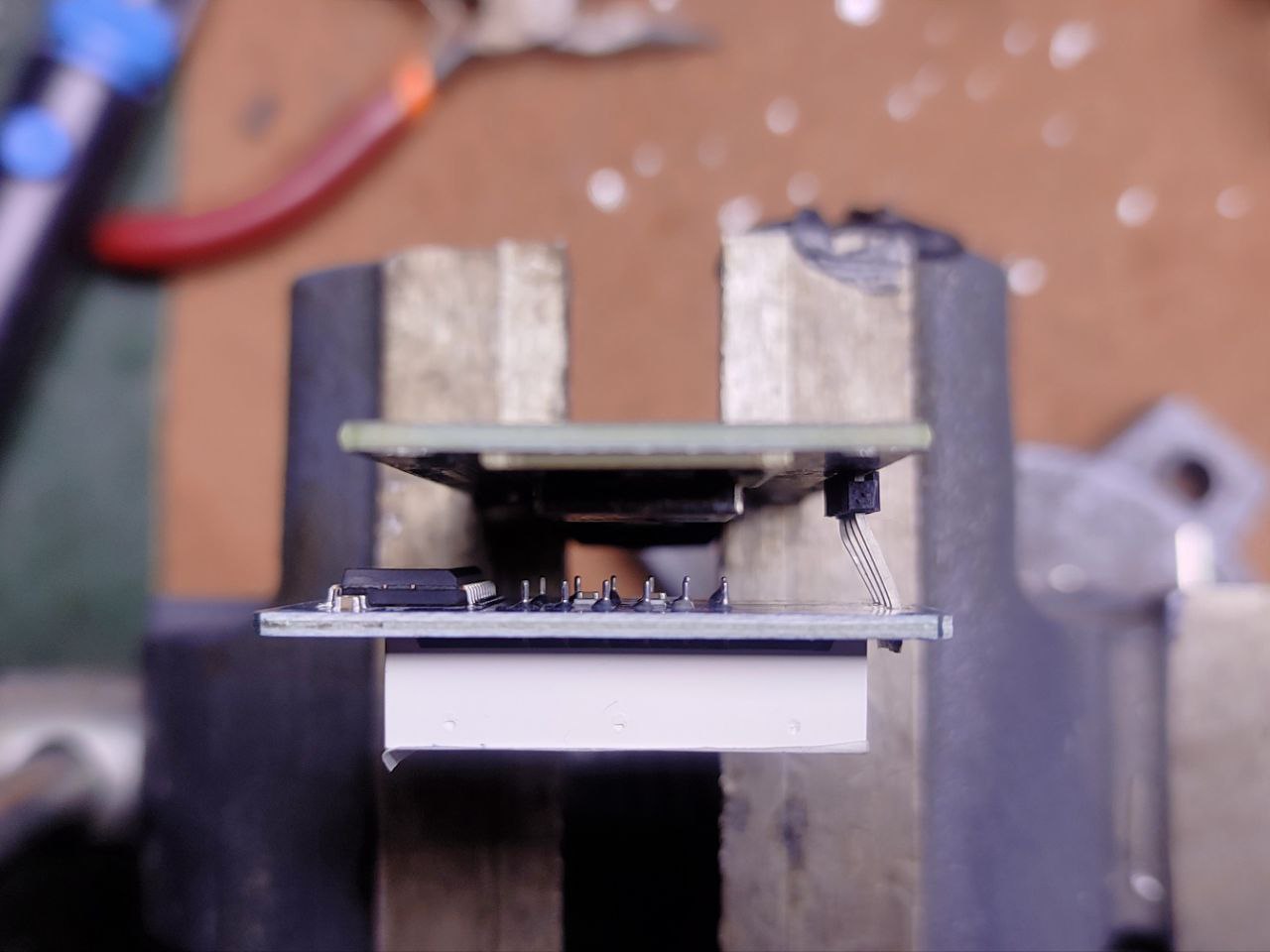
All installed:
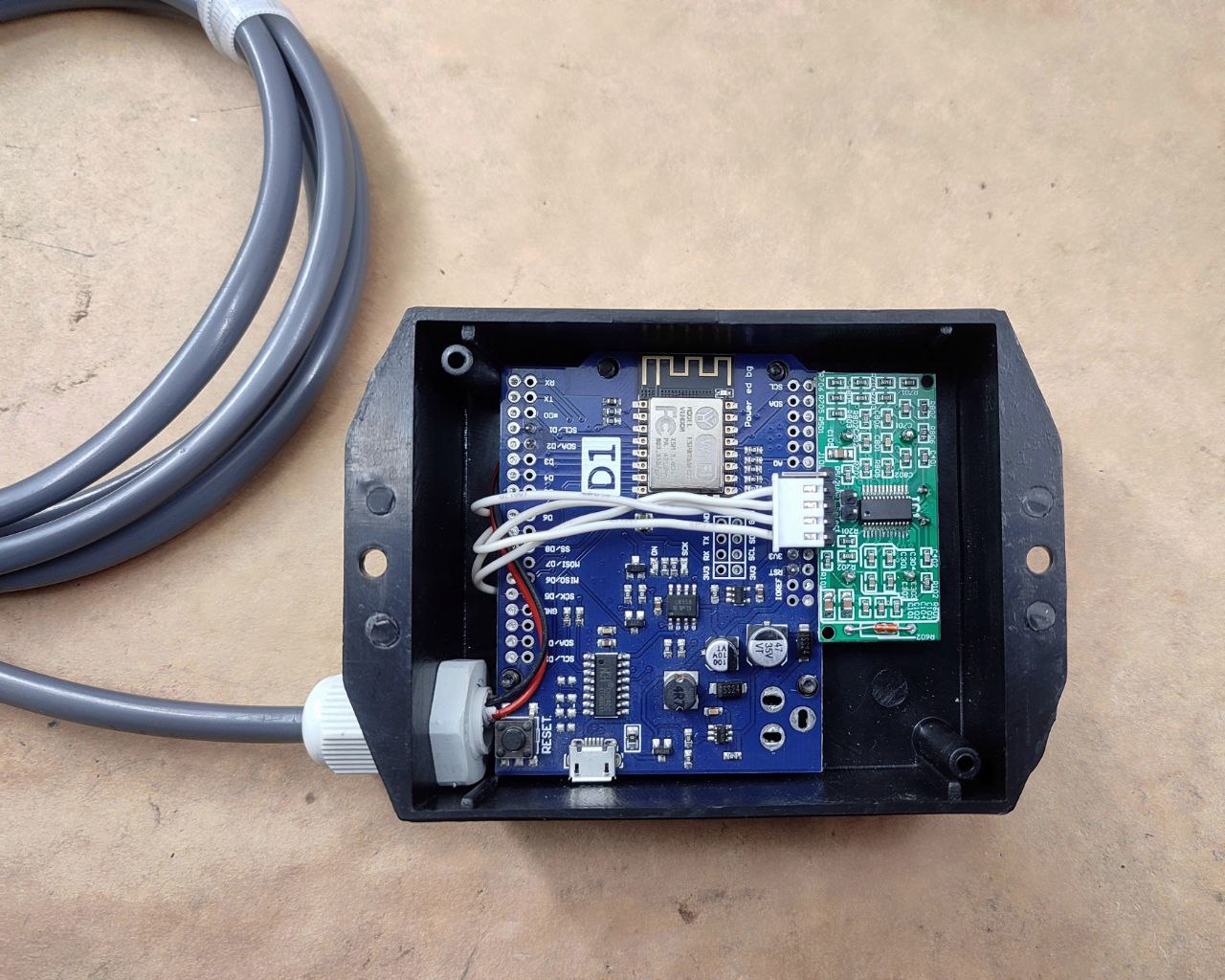
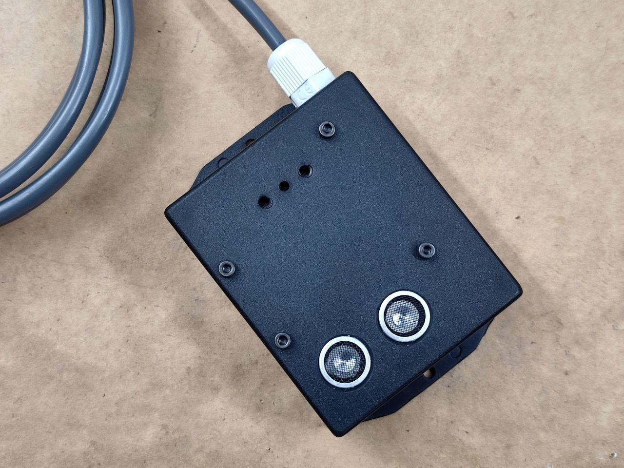
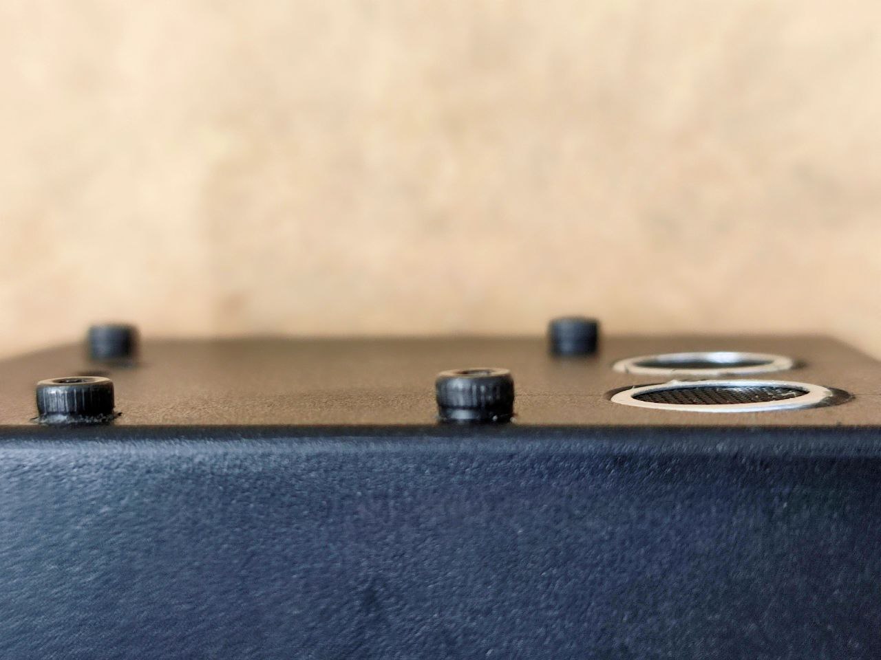
The WEMOS module is hard-mounted with M3 screws and spacers but it’s important that the ultrasonic sensor is not mounted through the metal cans, I used hot glue on the back of the PCB. Applying pressure or fixation to the metal cans will prevent the sensor from working properly, they must sit loose and free.
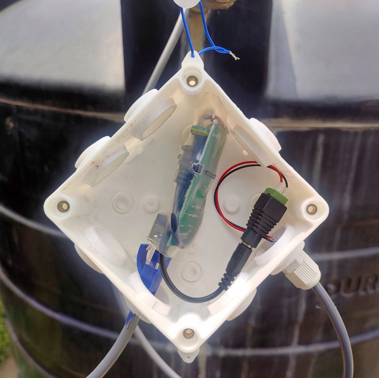
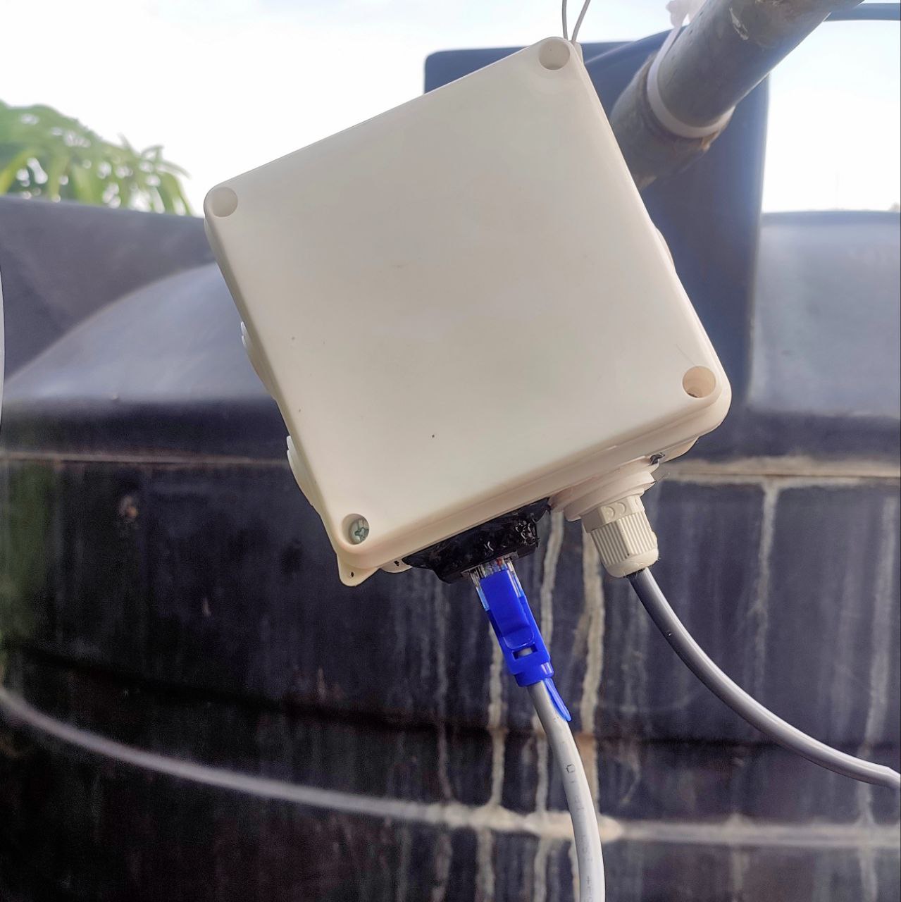
The POE adapter was also hot glued in a waterproof CCTV junction box:
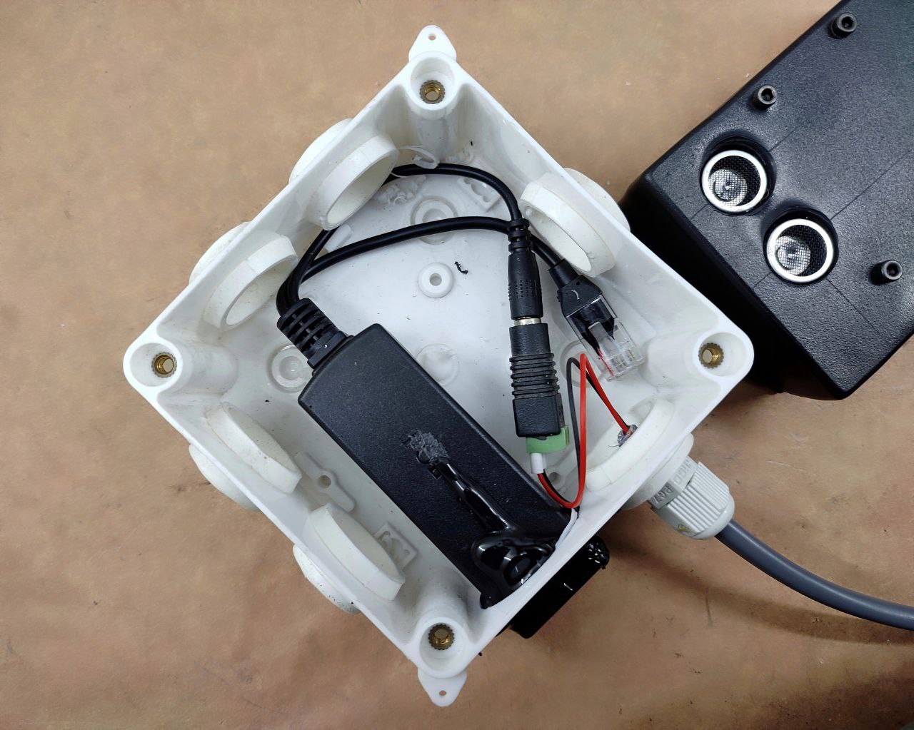
You can see the lines that I scored for drilling out the holes, they’re 16mm on one axis and 16mm & 39mm on the other axis. Drill out 16mm holes on the two intersections.
This is then mounted to the lid of the water tank, with a small bit cut out for the cable to pass through:
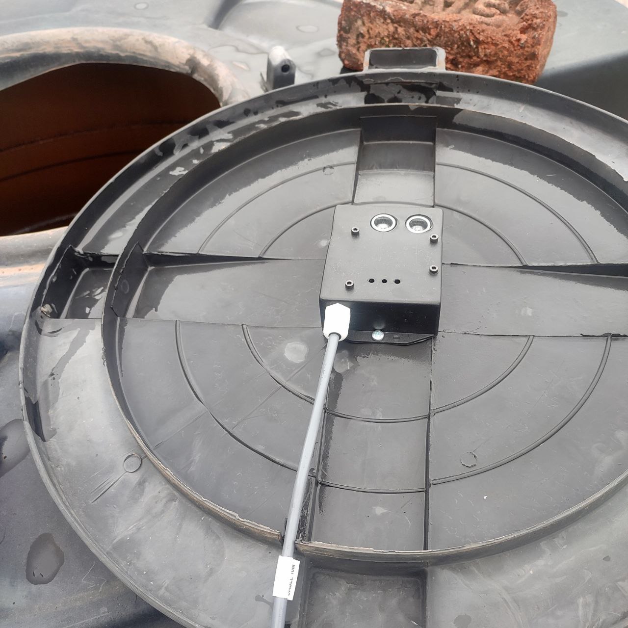
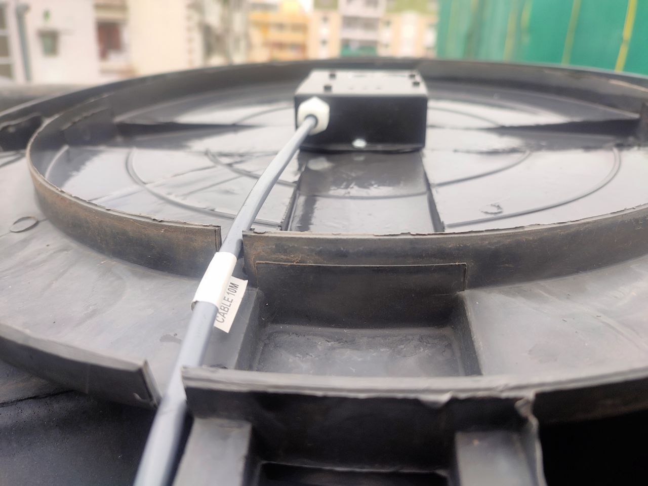
And finally the junction box is hung with a wire, with the cables pointing downwards to discourage water ingress during rains:
For the software, we’re using a custom build of Tasmota that incorporates a Serial to TCP bridge for Node-RED to access the sensor’s readings. This is because Tasmota does not currently support the UART mode of the US-100 sensor. You can compile your own or use the [ICODE]tasmota-zbbridge[/ICODE] pre-compiled binary.
Follow the instructions here:
while setting baud rate to 9600 with the [ICODE]TCPBaudRate 9600[/ICODE] command in the console. Be sure to setup rule1 to activate the bridge on boot with the command [ICODE]Rule1 ON System#Boot DO TCPStart 8888,192.168.0.10 ENDON[/ICODE]. The ip address should that of your self-hosted Node-RED instance (not covered in this guide).
PART2: THE CODE
This is the flow I’m currently using, you can replicate it or modify to your preference:
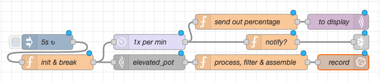
I called the overhead tank ‘elevated_pot’. You should have MQTT and optionally InfluxDB configured with Node-RED. You can delete the ‘record’ node if you don’t want or need the database.
Here’s the JSON for you to import into Node-RED:
(const String & payload) {
    reading = payload.toInt() / 10;
    if (reading <= 10)
    {
      bar.setLevel(reading);
    }
    Serial.println(payload);
  });
}
void loop()
{
  client.loop();
}
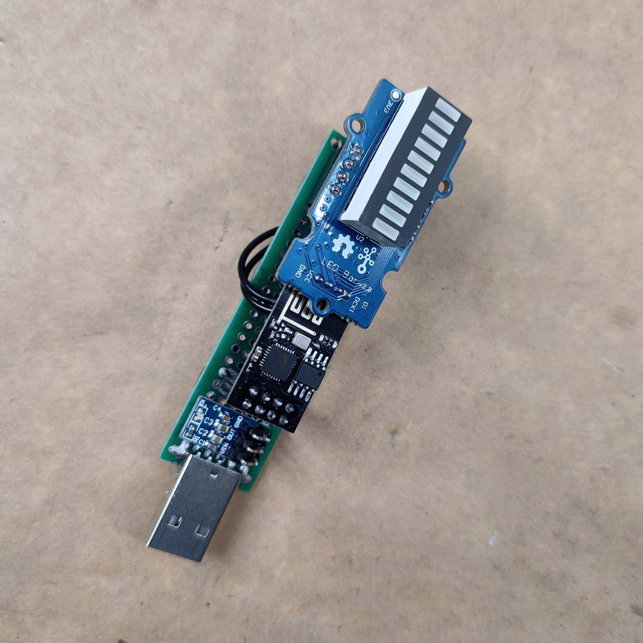
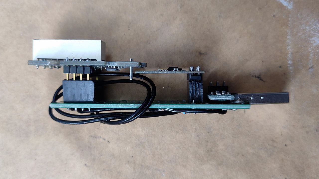
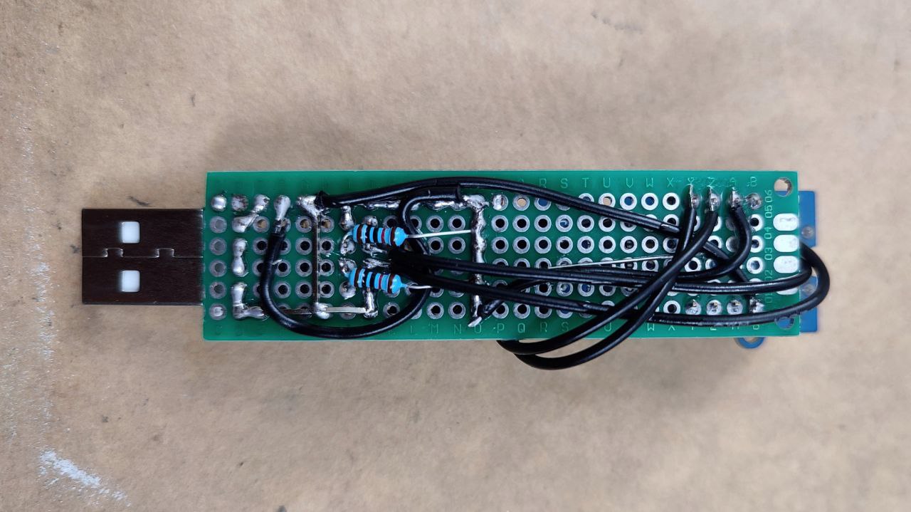
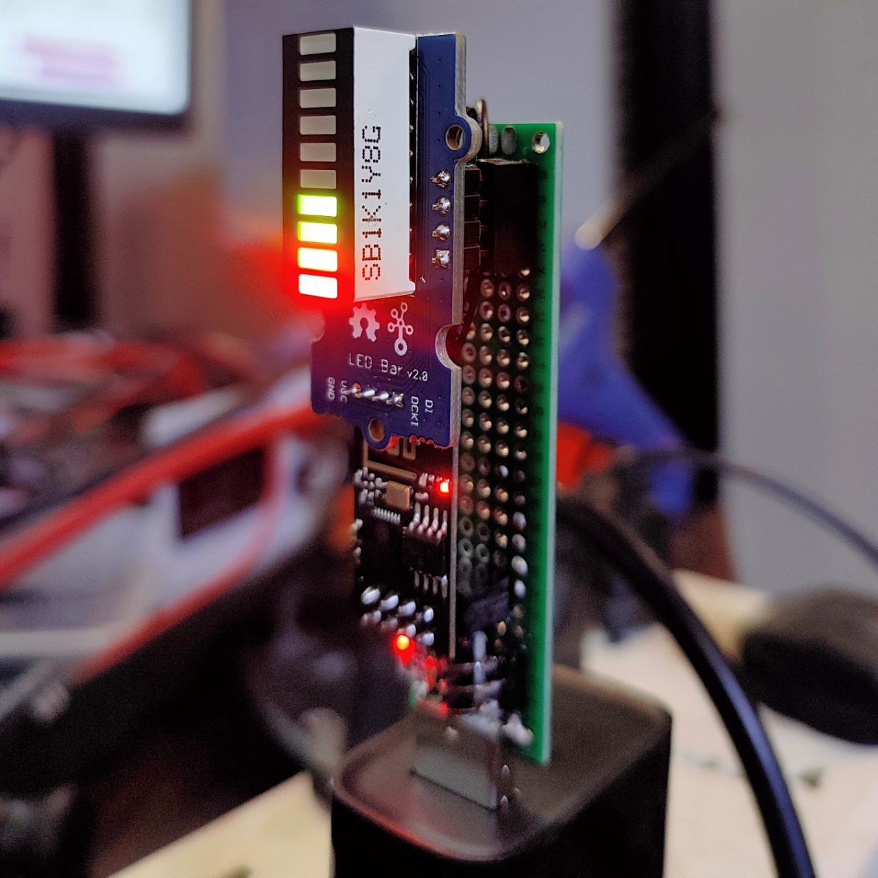
The serial connection is left on since the ESP-01 module has a blue LED connected to the TX pin, so it’s used a visual indicator that the module is working and getting updates.
We’re using the EspMQTTClient library that handles both Wi-Fi and MQTT:
The Grove LED Bar library in the Arduino IDE is out of date, so you’ll need to install it and then overwrite it with the updated unreleased files from github:
Be sure to experiment with the examples to learn more about those libraries.
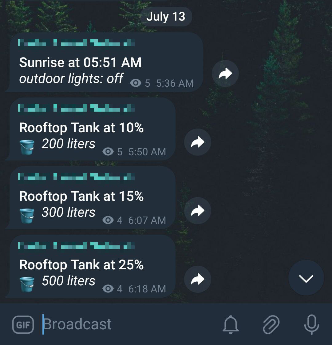
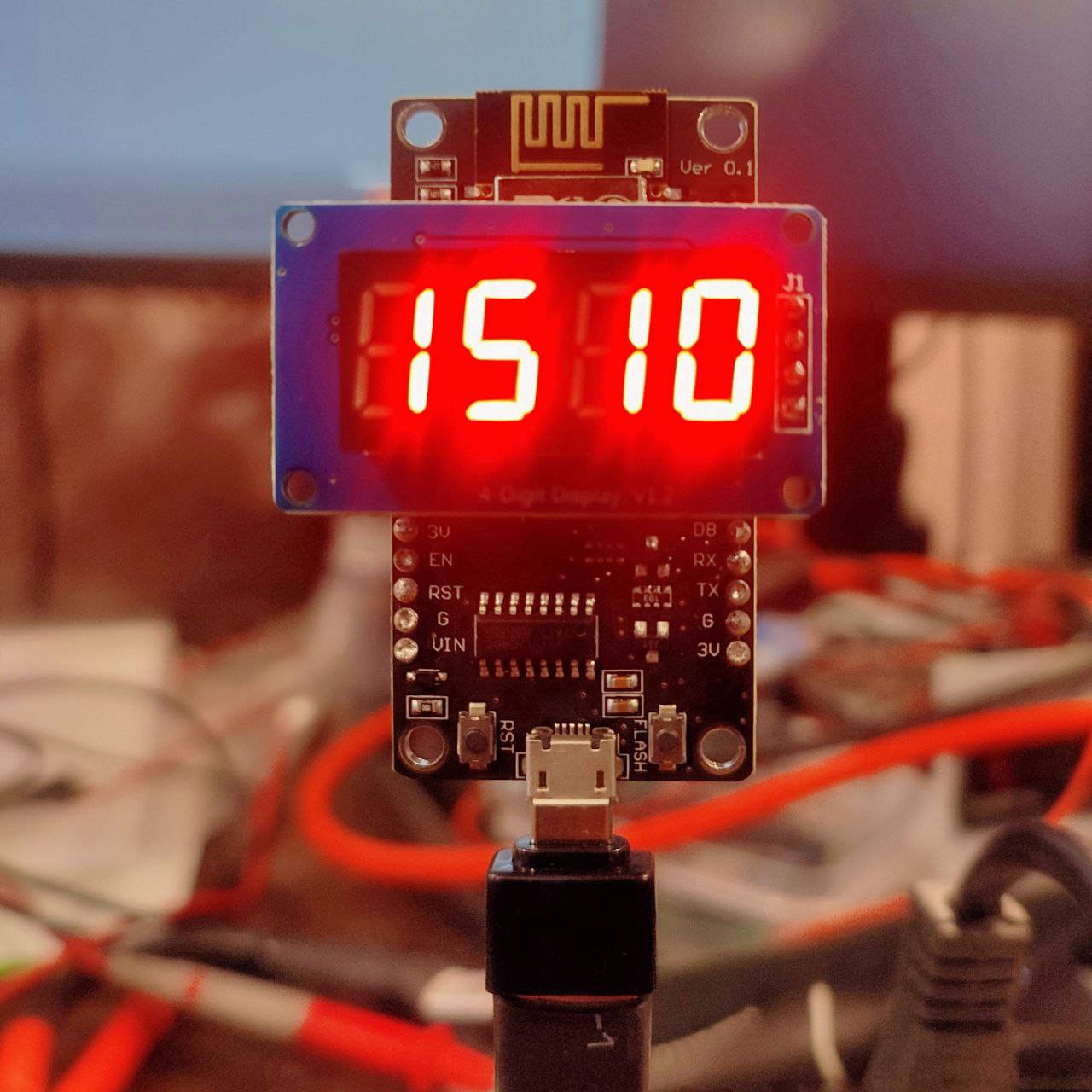
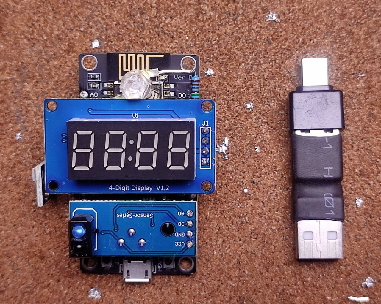
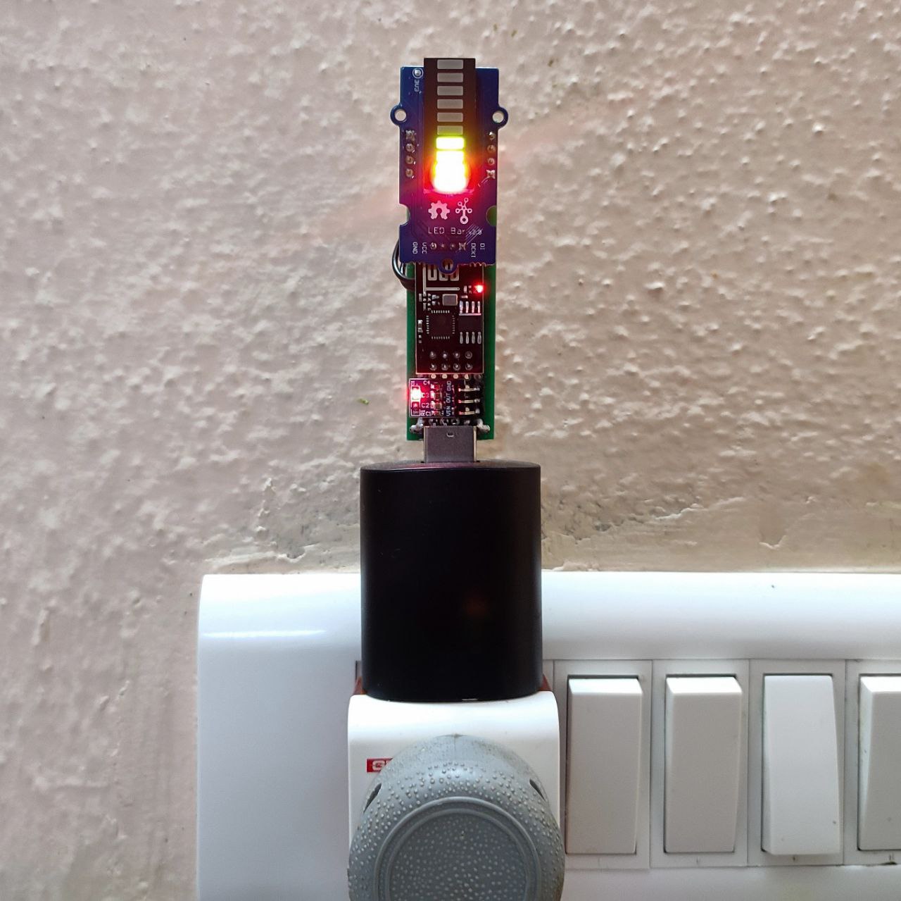
All configured and working, showing that the tank is 40% full:
Installed in the hallway for everyone to see:
This project has been bouncing around in my head for five or so years now. I’m happy it’s finally done, even if it’s just a prototype.
If I’ve skipped something or something isn’t clear, ask away, I probably did forget a few key details somewhere.
Attachments: