“Real earthing” involves digging a pit in the ground & bury the main earthing wire inside & is meant to protect the home from lightening strikes, static buildups & power surges. Equipment earthing is a bit different but it shouldn’t have any relation with transformer.
Heisen is correct in this instance.
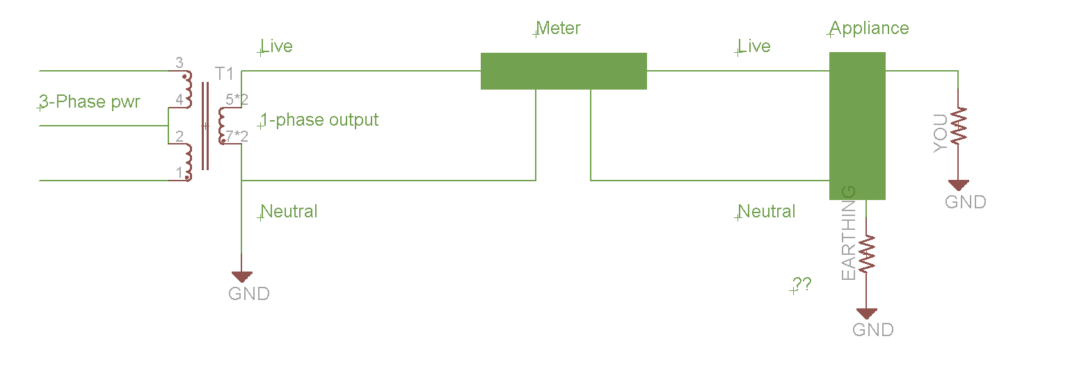
I talked a bit about this in #7. The ground/earth/neutral reference is from the utility scaffold on which the transformer is mounted. The earth and neutral bonding is done at that point, and after that the neutral carries the reference to your equipment (utility does not supply the earth but references to it, which is the source of your confusion). The ground is your safety net. The voltage difference exists because of how near/far the transformer is from your location, and how good the earthing resistance is - a function of the quality of the poles and how well the transformer is grounded.
The reason that the live line is dangerous is because it is referenced to earth, and humans can bridge the gap. But it is also the safety net for humans touching the live line in the first place. The danger of not having any reference at all is ‘float’, where untethered power supplies can drift to a dangerously high level above ground, and cause a current to flow anyway, sort of how lightning works but obviously at a much lower level and lower energy - still sufficient to harm or kill humans.
Wiring is old. Last changed 10+ years ago
All rooms have their own MCB
This is common across all sockets. Also it was a direct connection aka no extension board in between
-
I tested without 3 pin extn board. And still get the tester to light up
-
I also used a socket tester ( [Amicisense Socket Tester](’
) ) to get a quick glance of socket status and observe 3 places where earth was open and 2 places where PN was reversed. But the core issue is with 2 pin DC devices leaking current
-
Example
-
**6A socket **> Belkin 100W GAN charger > USB C port > USB C to C wire > its metal end > lights up tester + metal surface to ground is 100V
-
This is same socket whose PN , NE , EP readings I have shared .
If I understand correctly, the N-E bonding is to be carried out by the utility company and where the transformer is placed. ?
Additionally can the consumers bond N - E to any earthing earth source .. let’s say before the the PN are attached to the electricity meter ?
I think a diagram will help here:
The three-phase transformer is not an accurate representation, it’s just what the schematic library had to offer.
All currents, including fault currents to earth, will find the path of lowest resistance. Assuming you are touching the appliance (which is assumed to have a live wire shorted to a metal enclosure), the resistance to earth - all the way back to the neutral of the utility transformer output - will need to be lower than your resistance to the same point.
2 Likes
First of all lots of thanks @@cranky @@rsaeon and others ; for your time and efforts for sharing useful info.
So what could be the issue here
- Neutral is putting up resistance and thus fault is not going back.
- And NE bond at Transformer is not helping either
And how do we fix this ? Can we bond NE just near home ; which is closer than the transformed ( and before N is attached to meter ) ?
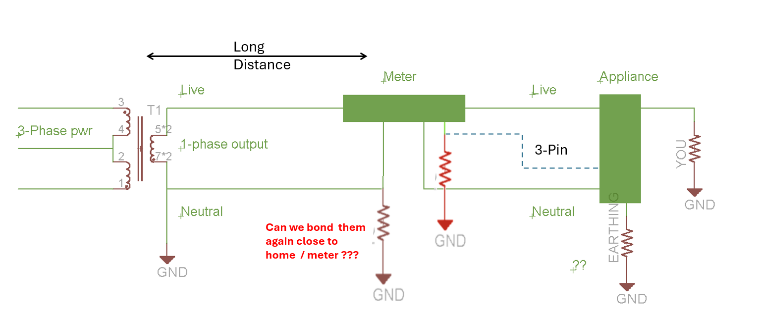
The bonding you talk about at your home is the earthing rod. Its purpose is to bring the apparent resistance value as close to zero as physically possible. The reduction in resistance from your 3-pin outlet to the main entry board is not sufficient to qualify as a major change, and is half-measures at best.
Multiple ground connections are not an issue, so you can do it from your own flat as well, all the way down into a fresh pit.
Be aware though that in this kind of implementation fault currents will still seek the lowest possible resistance, so there’s a rare possibility that other fault currents not generated in your home but sharing the same utility phase, may find their way into that earth and may give rise to strange noise in audio and A/V equipment. We’ve had this issue with clients who redid their mains wiring with very heavy gauge wire and then complained of noise in their speakers.
Your job is to get every resistor except the last one (YOU) to zero as far as possible, and your body resistance as high as possible - insulating yourself from the floor, for example. this will keep you safe in the case of grounded appliances developing a L-E fault.
This will not solve your tester lighting up or your tingling, FWIW. It will probably lower your N-E voltage to within an acceptable margin, if the utility has done their job properly. For that, you may try reversing the charger polarity to get C4 (shown in one of earlier posts) connected to Neutral instead of Live. It might work, or it might not.
1 Like
Additionally I will check the charger at some other house/place to rule out any issue with it.
i have all my usb charger leaking voltage, need to check earthing, its a great great discussion, one of the main important point
people spend more money on costly electrical applicanes but they dont want to spend little more on proper earhign, very sad
its because mainly all local elctrician who do wiring, they dont know much about earthing, and they do not educate home owner
proper earhing cable would save lot of time and future cost
1 Like
Please shed light on the new system of earthing using compound instead of using salt and charcoal. Some use gi rod with chemicals inside. And I read that Copper erodes with the added salt.
Would appreciate your knowledge for a permanent maintenance free earthing for my solar and lightning arrestor diy setup.
The neutral wire fell off the pole the other day, resulting in this:
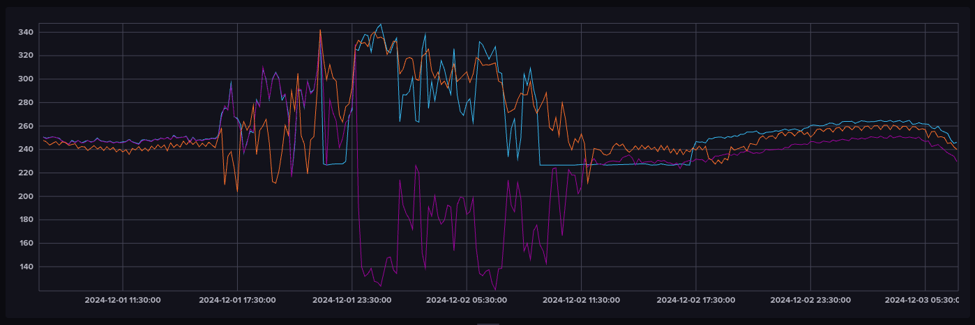
Two phases went over 300, one phase went down to 120. The electricity workers here don’t climb poles after 5pm so I had to wait until 11am the next day for it to be fixed, and I paid Rs 1000 even though this affected an entire block of houses and flats (apparently my neighbours didn’t care enough). I’m in an area where the residents don’t pay taxes (slums) so we’re not prioritized when these things happen.
I switched over one of the smart plugs to the other phase to better understand what was happening (pink line). Blue line is the home lighting inverter — I switched that over to the server ups/inverter so my parents would have reliable power while they were awake and then put it back while they slept then again back after they woke up. I got about four hours of sleep that night because I needed to monitor the cluster (which I needed to keep online because of cyber monday weekend).
This isn’t the first time it’s happened so now I’m wondering if I should get a neutral pit dug because I lost a lot more than Rs 1000 during those ~17 hours of unreliable power.
This is the work they did (the lower joint is the neutral, the top joints are the three phases):
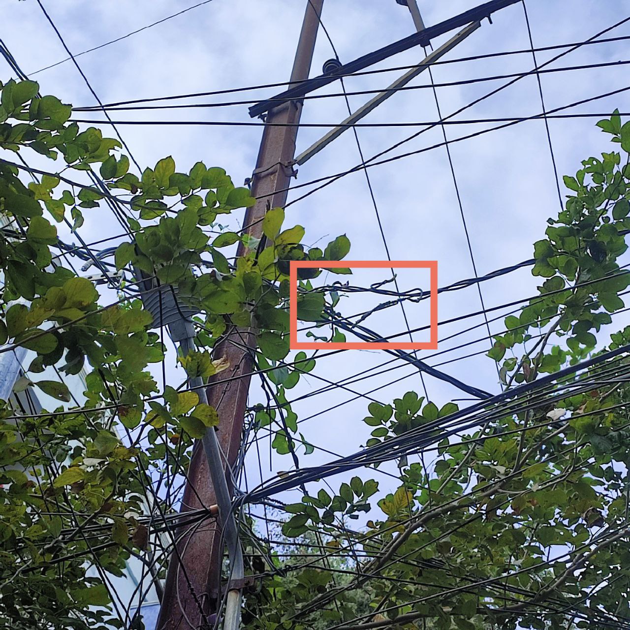
Despite the less-than-stellar workmanship, their terminology was flawless — “we found the neutral jumper was disconnected, it is now reconnected.”
My house uses 0.75sq mm wire to connect from mcb box to outlet earth pin. And thicker wire from mcb box to earthing pit.
Question is, why is the wire so thin? Is it fine? While Phase and Neutral wires are of 1, 1.5, 2.5sqmm.
Been there, I know your pain. I had 320v, 280v and 100v or something in the phases in dec 2017. It resulted in my Sony lcd failing. The high voltage lasted a full week, no one from the 5 streets the transformer is connected to complained. It took a lot of escalation to finally fix it happened again a month later and there after once every year or so. This happens when the neutral wire or contact area is loose or has carbon deposit after arcing.
I thought of this too at that time. But they said its illegal to do so. Technically the neutral wire is nothing but the ground to the transformer. But even if you dig a neutral second earth pit, your pit will now act as a earthing/neutral for the entire houses and streets the transformer is connected to. That means unwanted electricity flowing from ups/ inverters connected wrongly, lightening, phases shorting due to crow or branches resulting in 460v. So my advise is to either go off grid or keep ask the Electricity Board officials to get their shit in order.
Sadly it’s the same even in Tier 1 cities. These people had the audicty to say the voltage is fine by putting a tester.
If you want to protect your house from a such high voltage spike use a SPD and then connect it to the output of a ELCB/RCBO. Now when the spd gets a voltage above 275v it will dump all the current to earth. This forces the RCBO to trip and also reduces the failure of the SPD. You will off course get lot of tripping each time the voltage goes above 275v. But in my case I put a auto reclosing RCBO that I got from aliexpress before the ban. The Auto reclosing RCBO would automatically moves the mcb lever after a trip and repeated trip will lock it out and will need manual intervention for safety.
I had posted about this before also in some thread.
Earth needs to have the lowest resistance. As the current and voltage builds up, the resistance of the wire increases and electricity flows in the path of least resistance. So if your body has lower resistance than the earth wire then you will get a lethal frying shock, unless you have elcb/ rcbo/rccd.
So earth wire should be the same size as the live or neutral wire. There is a reason the earth pin is bigger on a 3 pin plug both in 5a and 15a plugs.
2 Likes
That’s brilliant advice, thanks a lot.
Offgrid is the long term goal, but these things happen so often that I think I need some kind of neutral disconnect/changeover at the meter. But it’s probably not worth the risk.
One of my UPS was happy with upconverting the 120V to 230V which was a huge relief and it let me keep half of my machines online that night.
I did get a sense of how to better set up the power conditioning appliances I have though. Need to get a stabilizer that can handle >350V, an inverter in wide input or eco mode so that it doesn’t trip often then this online ups that I have as the last part of the chain.
Stabilizer will handle high or low voltages, I already have a 5kVA one so maybe add another before this that’s rated for higher voltages (this one can handle low voltages fine). Inverter will handle extended power outages, and the ups will handle power cuts/spikes/irregularities.
Gotta put some thought into this.
This exact same thing happened when I called them.
I believe up to 4 volts measured with a high impedance meter is acceptable.
This is interesting. I have a similar problem where I am trying to determine if I have a Ghost/Phantom voltage. I am living in an apartment. The meter is connected to the main MCB which is again connected to an ACCL (Automatic changeover with current limiter) for the DG and then is input to my flat to an RCCB.
When I have my main MCB switched OFF in the apartment basement and my RCCB switched ON I get a 2.2V between Live and Ground. My RCCB trips when I measure between Neutral and Gnd. Between Live and Neutral I get 1.2V.
When I put both MCB OFF and RCCB OFF I get 0V in Low Impedance setting. So is this Phantom voltage due to all the wires coming in the basement. I and my electrician measured using a tester in the basement on other people’s installation neighbouring mine and the tester glows on Neutral and Live even when the MCB is OFF. My electrician is reluctant to troubleshoot further because it involves turning OFF power one by one to trace. Any help here would be appreciated.
It is not abnormal to have some inductive coupling of AC voltages between cables in close proximity, these are usually stray coupling of higher frequencies. This is not an issue in my understanding.
The reason for the RCCB tripping is because there is sufficient imbalance in current between the lines, you can use a high value series resistor, about 2kohms, to check the voltage without causing current imbalance. A clamp meter will also work without causing any current to flow.
@cranky : That is what I am trying to determine whether it is a Phantom voltage or not. The one thing that I am worried is that it is enough to power a neon tester(not sure what the power draw is). So I am not sure whether it is safe. One plan is to try to connect a proper light bulb (load) to see if it is enough to power that. Does this make sense? Also does it give a tingling sensation if touched? The problem is that I do a little DIY of simple switch changes etc and I don’t want to get energized after turning of my flat’s RCCB and the MCBs without turning OFF the main MCB.
Yes. I understood that it is normal. Unfortunately I don’t have a clamp meter currently.
Without LoZ mode, I get a voltage of 123V between Live and Gnd and 133V between Neutral and Gnd. Between Live and Neutral I get 6V. From what I have read it is normal inductive coupling and the voltage being nearly half of the actual voltage. It is not enough to power anything else.
No way to tell without touching. I wouldn’t advise it.
It usually is.
It seems to respond to loading, which is good. You can try some aftermarket mains filtering on the line, this usually tackles the HF components properly and the voltage should basically disappear. It does require a bit of load to function though.
@adder So earth wire should be the same size as the live or neutral wire. There is a reason the earth pin is bigger on a 3 pin plug both in 5a and 15a plugs.
This is surprising, and honestly, shocking (pun intended) news to me.
Often, electricians (even licensed ones) run a slim, single-core copper or aluminum wire as Earth wire. Meanwhile, the Live - Neutral wires are of thicker gauge.
What you mean to say is that households must use a same or thicker gauge wire for Earth compared to Live-Neutral as it will lesser resistance and hence ensure current passes through Earth wire in case of leakage prevent shocks to humans.
{Edit}
It appears the Earth Wire should be at least a certain thickness to bear the full load at least for a short amount of time without overheating and breaking.
What my layman analysis suggests is run an EXPOSED Aluminum strip to the Earth pit. It should be cheaper than a copper wire with equal or higher gauge than the Live-Neutral wire. This way, the Earth wire won’t overheat and safely carry the leakage current to Earth until Safety MCBs kick in and disrupt (or cut) the flow of Electricity.
Please advise if this is OK.
Normally , the phase and neutral wires are thick , but the fuse wires are thinner than the earth ones .
The earth is designed to blow the fuses or trip the MCB . That is my understanding .
With regard to laptop chargers , or SMPS type power supplies this tingling effect is felt if there is no earthing . With transformer based power supplies that effect is not there .
In rural areas for temporary lighting , we connect the neutral wire to ground and the live wire is “hooked” on to the main transmission wires on poles .
Once we were playing a cricket match and the light got dimmer , so someone had to piss on the metal rod to make the “contact “ with the neutral connected to the ground . It is for the same reason that charcoal and salt are added to pits to keep it moist so that conductivity is maintained .
If you get a tingling effect , check the earth rod and try adding a bit of water on the rod and check again to see if the earth works .
1 Like
No, The job of earth/ground wire is to take body current on appliances, or leakage to ground and prevent electric shock or blow out of appliances due to surge.
MCB trips when there is overload on circuit, not the job of Earthing/ground.