Lately I have gotten into a new hobby of fiddling with mechanical keyboards. It all started with me fixing a TVS Gold that was handed to me. It soon developed into fixing more keyboards and improve them.
I had the initial reservation that anything less than a full size keyboard with 104 keys or at the worst case, a TKL is just a gimmick. It just looks good and saves space while not offering any benefits. Oh how wrong was I.
This is when I bought an Ajazz AK33. A compact keyboard with almost all keys as of a TKL. It was great!
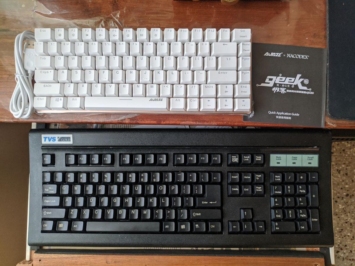
I then attempted to swap out the switches with Gateron Yellows and I ended up killing the keyboard. Danggit.
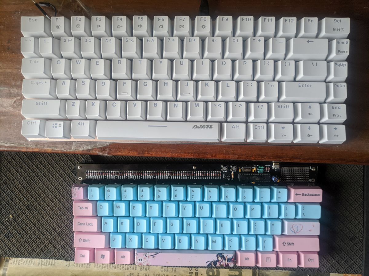
Fast forward couple of months and I got myself a Tartan 60% keyboard kit. I was still reeling with the loss of the Ajazz so I got most of the components soldered onto the PCB before I received it. I got the kit, assembled and soldered in the switches. The keyboard felt great! The lack of arrow keys was a bit irritating to begin with but I got adjusted to using layers.
Once I found some confidence in soldering keyboards, I attempted to resurrect the broken Ajazz by doing a handwired build. I bought a bunch of diodes locally and arduino Pro Micros from BM-ES. Each cost 345rs and they had free shipping for orders over 1000rs. So I ended up purchasing 3 of them instead of one to save on shipping! Penny wise pound foolish eh? . It went surprisingly well and everything worked on the first attempt!
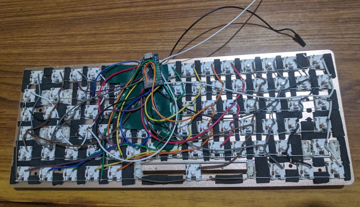
Wow, who knew handwiring a keyboard will be so easy? (or so I thought...read more to find out)
So, one of the pro micros was used up on the Ajazz and I was left with two more. This gave me an idea to make more handwired keyboards. But what should I do next?
The answer came with this video
This made a lot of sense to me. By this time, I had got pretty used to the Tartan and its layers, so much so that I was not missing the arrow keys by much. The decision was taken - my next keyboard would be a Planck.
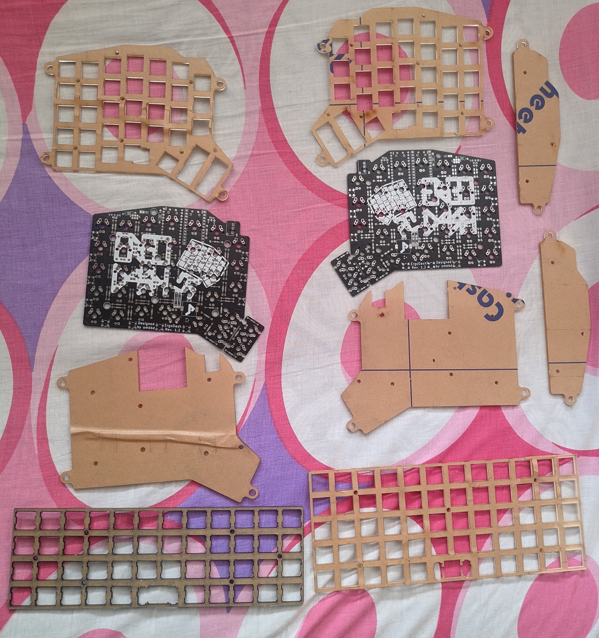
As always, the first step to making a handwired keyboard is to make a plate. I first wanted to go with a brass switch plate however it was incredibly difficult to get someone with a laser cutter and would be able to cut metal.
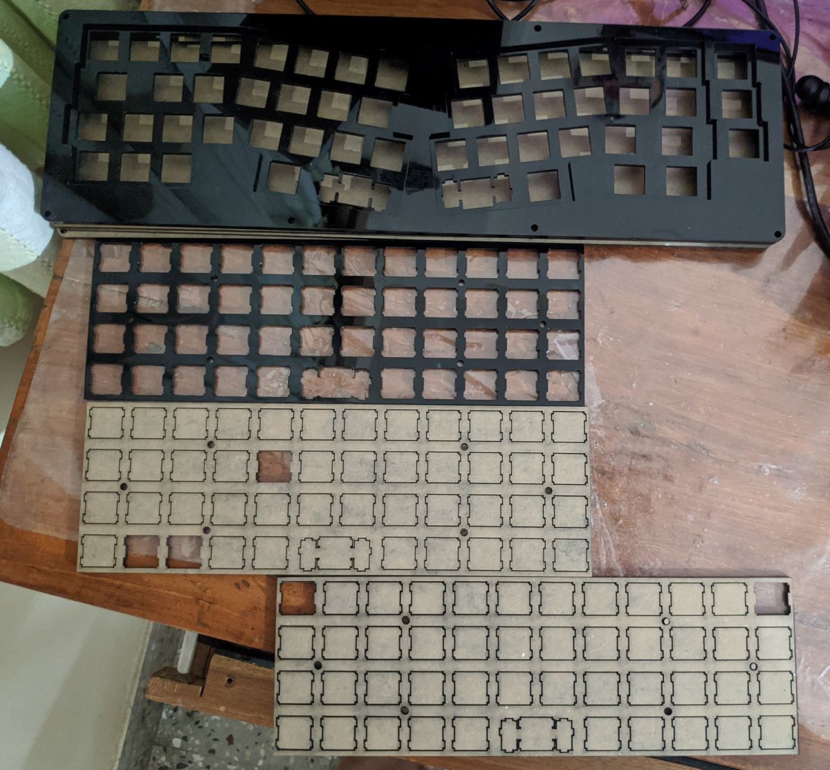
After looking around fior a while, I gave up. Next best option was to get an acrylic plate done. I found another person who wanted a custom keyboard cut out of acrylic, we bundled our orders together. Soon, the laser cutter got laser cutting
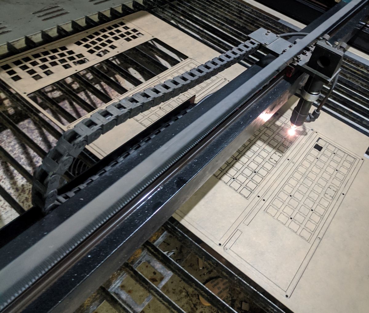
Soon, I have a few blank planck switchplates to play with!
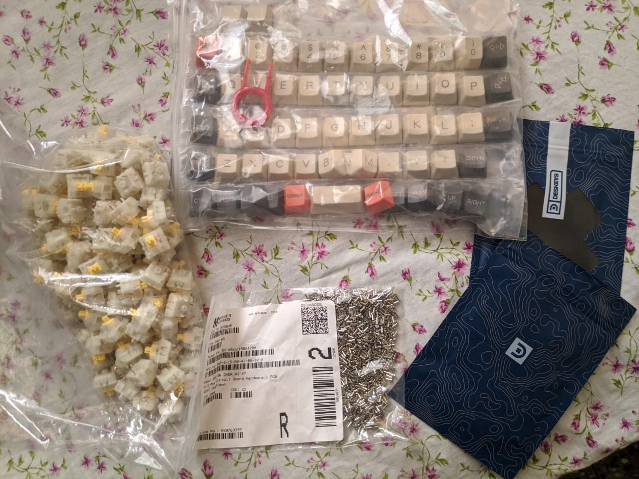
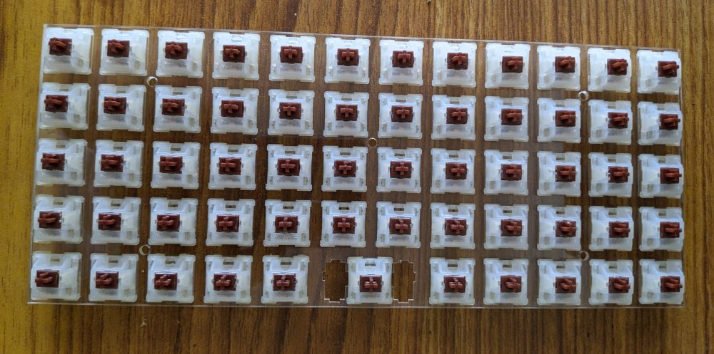
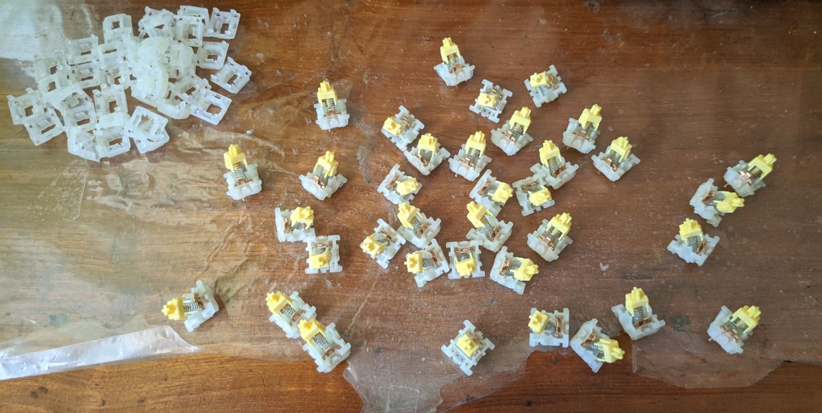
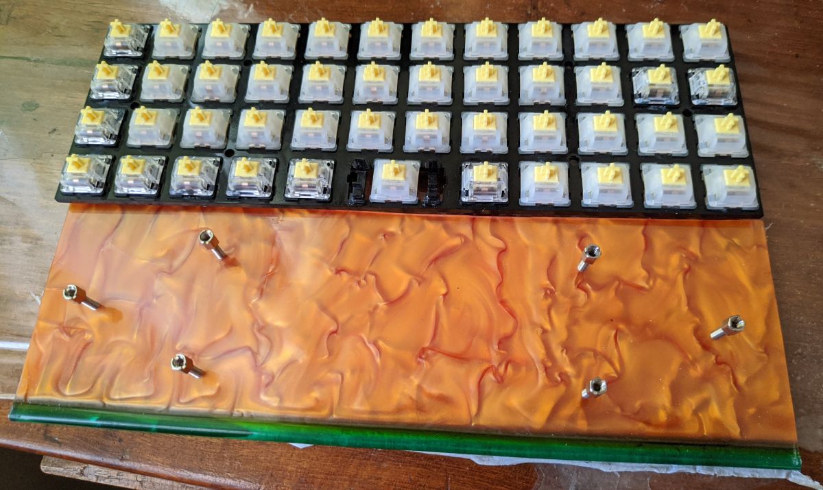
Next step was to prepare switches - I went with a combination of Gateron Milky Yellow and Clear Yellow switches. As usual, the switches were opened up for lubing
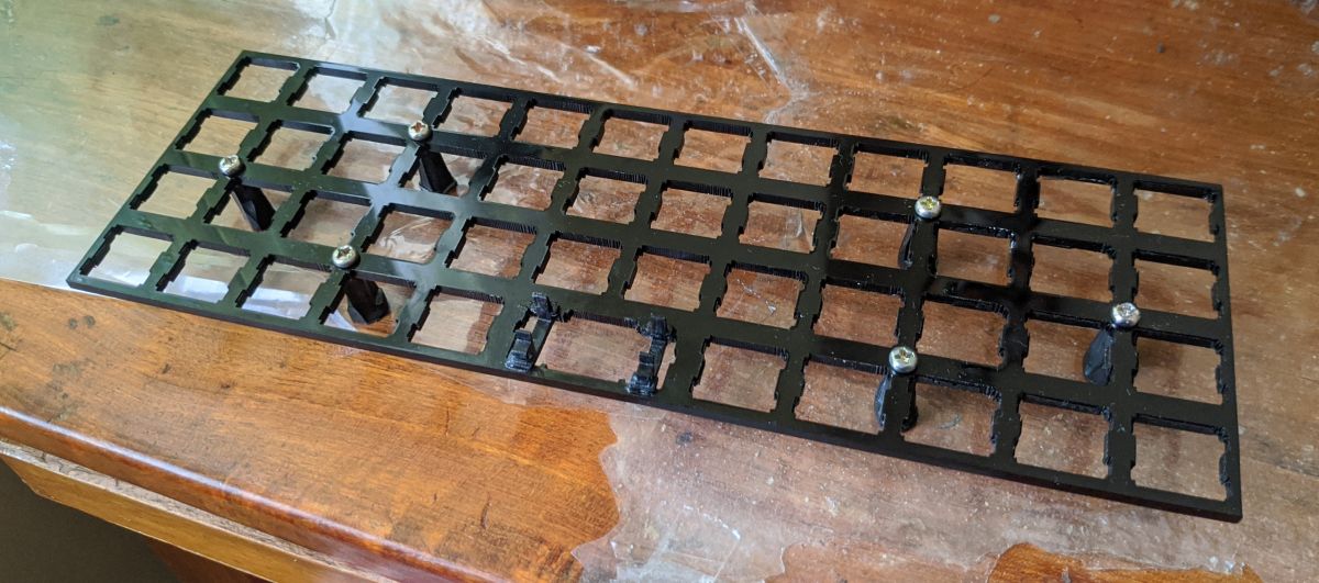
Fixed a pair of costar stabilisers and temporary stands
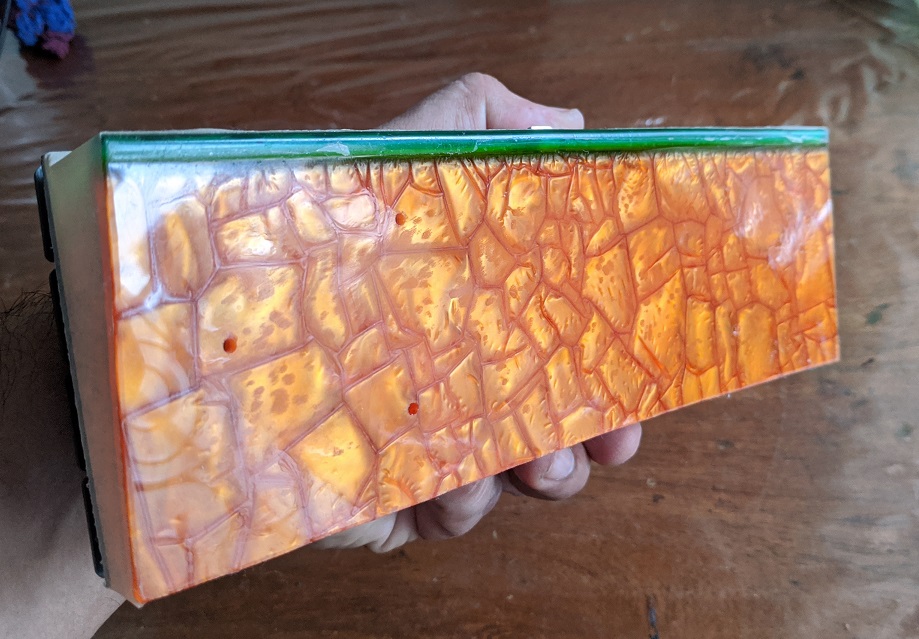
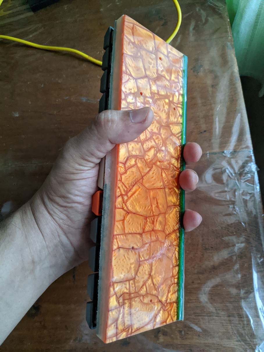
Now, for the case. My plan is to do a wooden case for it. However that would take time. Coincidentally, I found a scrap piece of acrylic which was almost the same size as the planck!
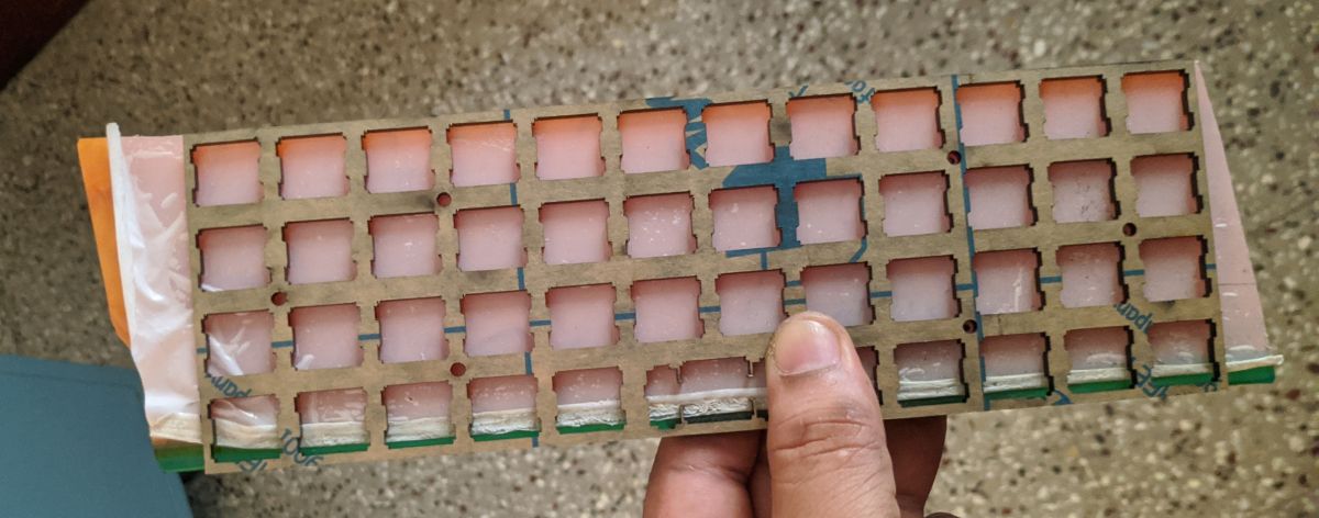
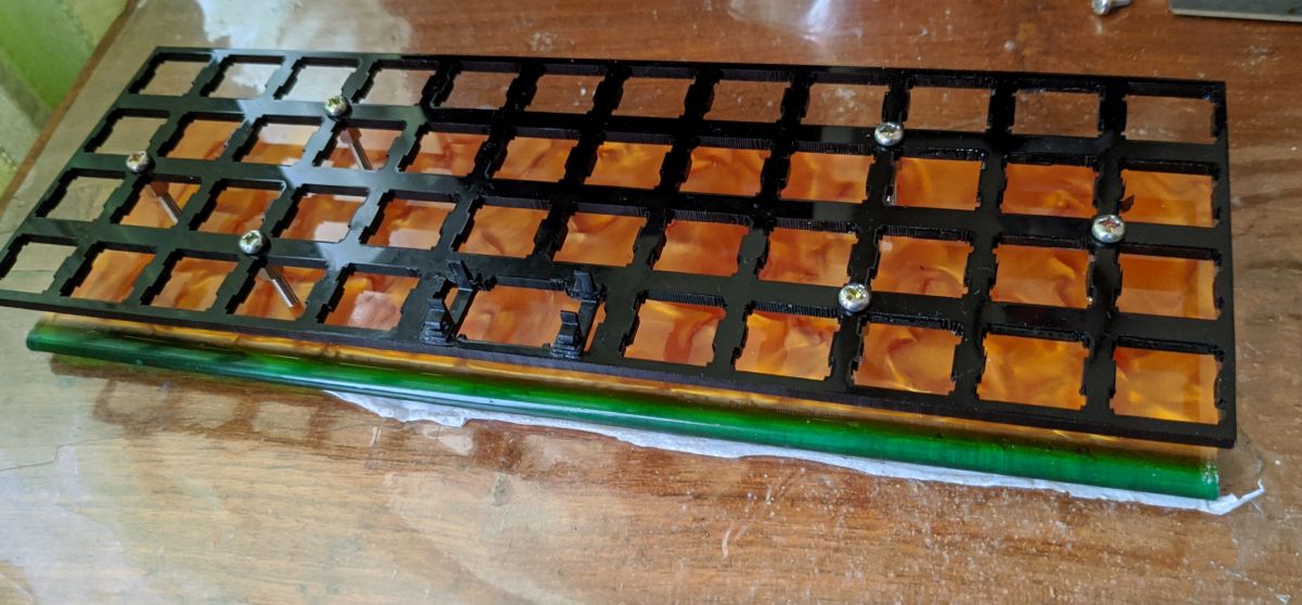
Lil' bit of chopping on the sides, mark and tap holes for standoffs. The base is ready.
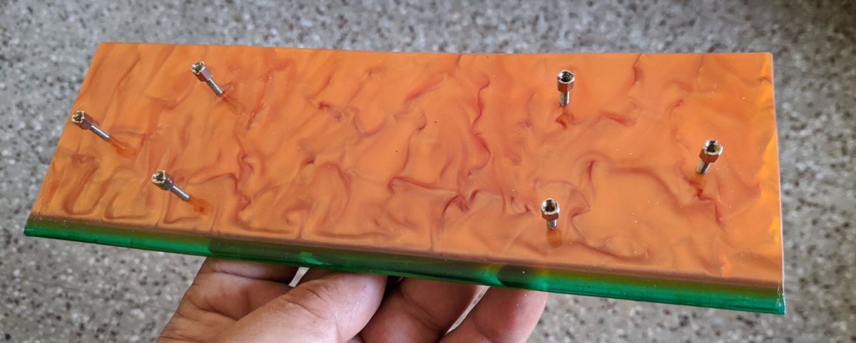
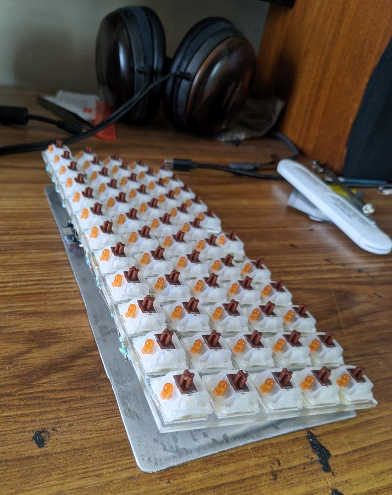
Yup they fit. looks half decent too
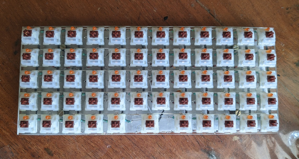
Switches added and glued on so they don't pop back out
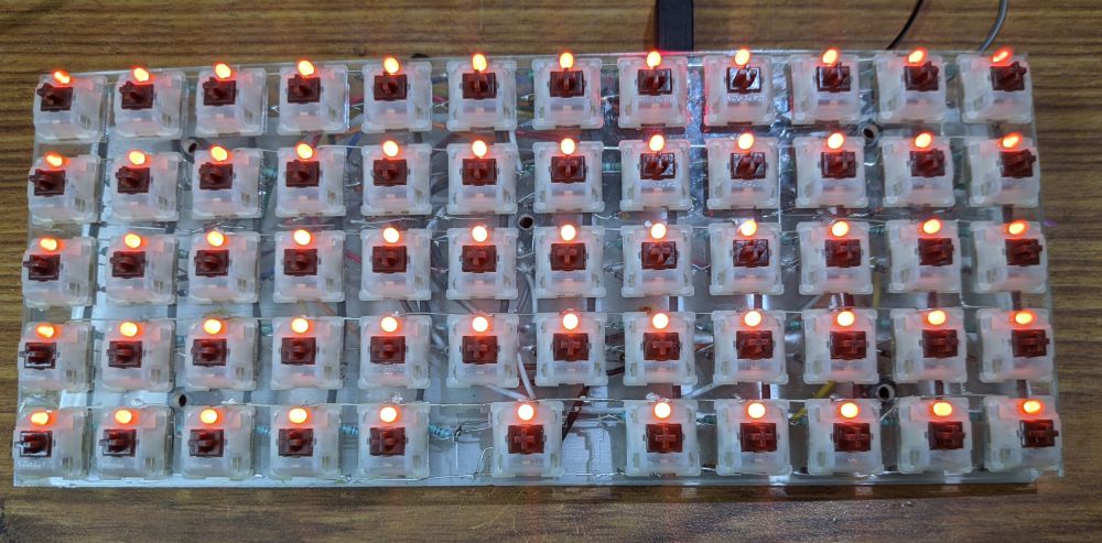
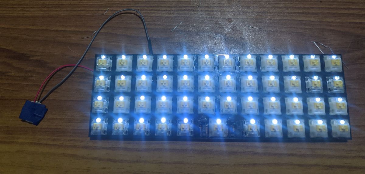
Next step was to add the backlight. Yay it works!
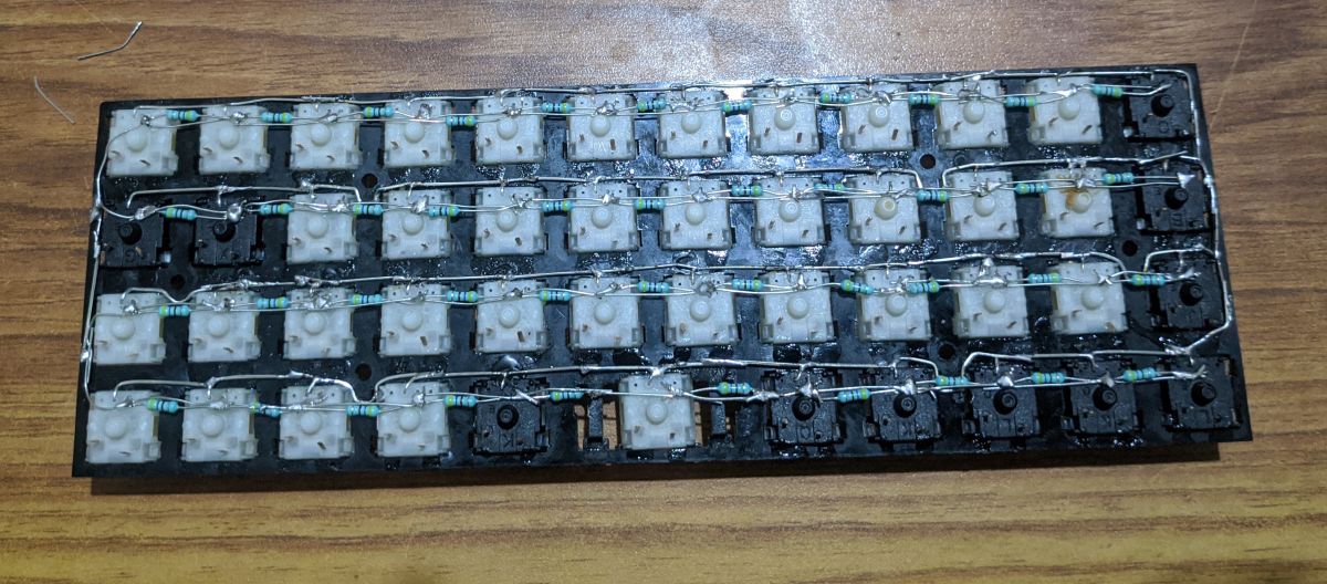
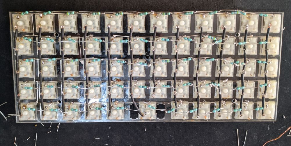
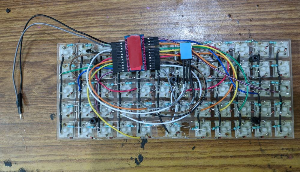
Next was soldering diodes to the rows. I've been trying to keep the soldered lines very compact and I think I've been doing a good job at it!
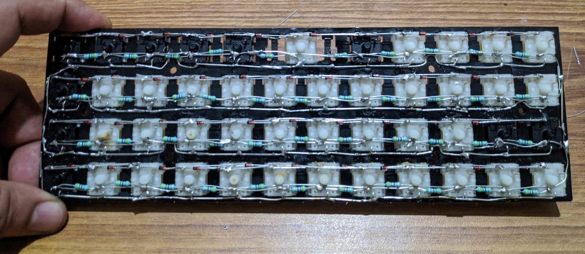
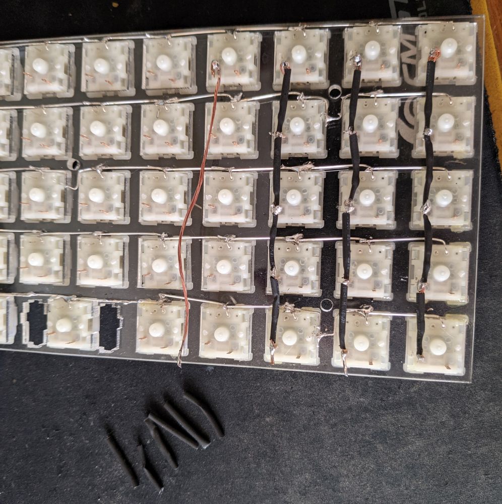
For the columns, I wanted to try something different and use enamelled wire. The enamelled wire are used for motor and transformer coils; unfortunately I had the thickest ones arund 1.1mm thick. I had to file off the enamel to make electrical contact too.
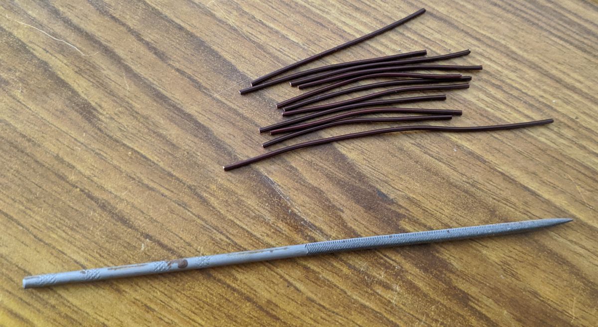
Soldering those thick enamelled wires was pure T O R T U R E. This clearly was a bad idea. But hey, they look good!
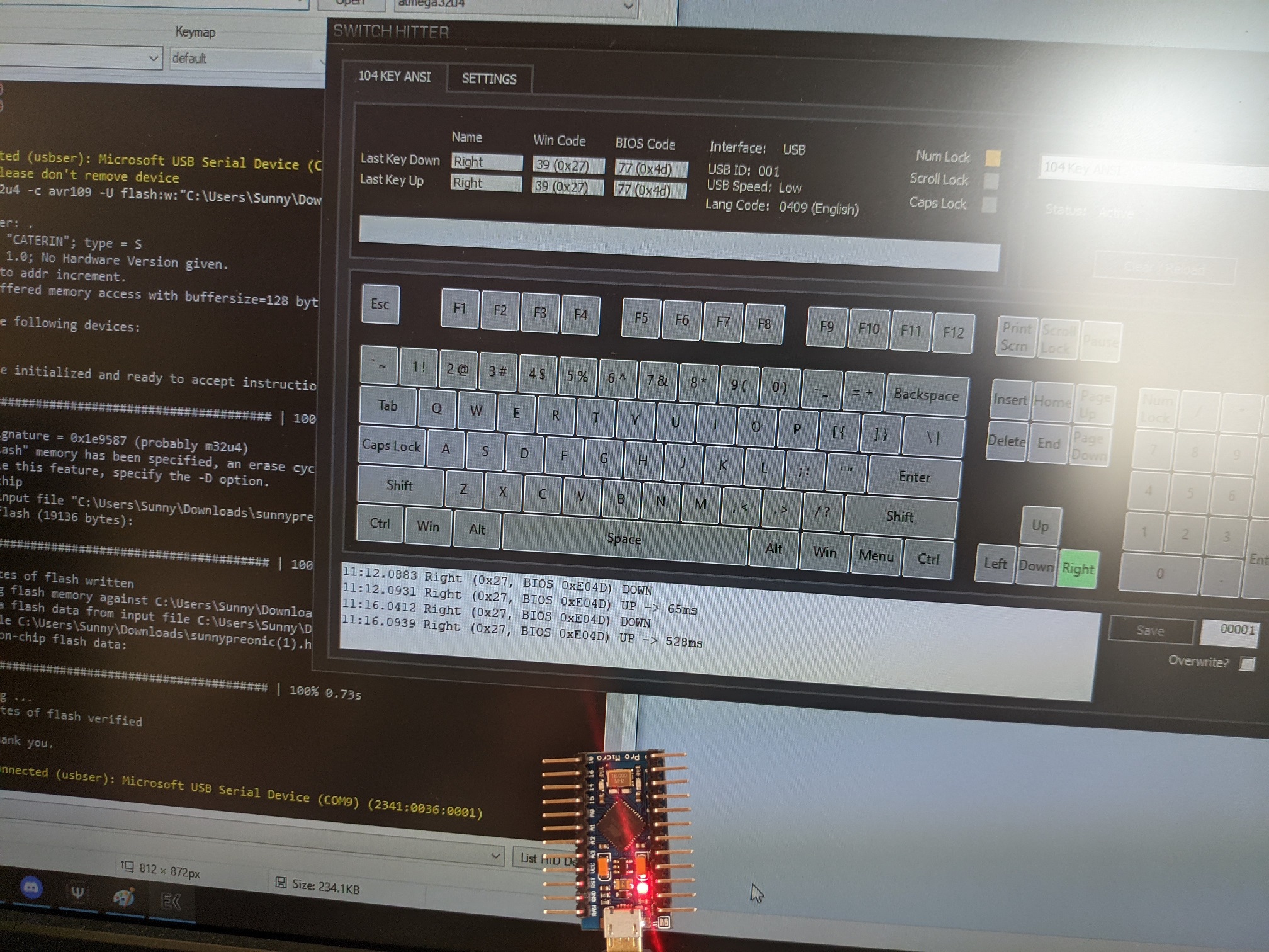
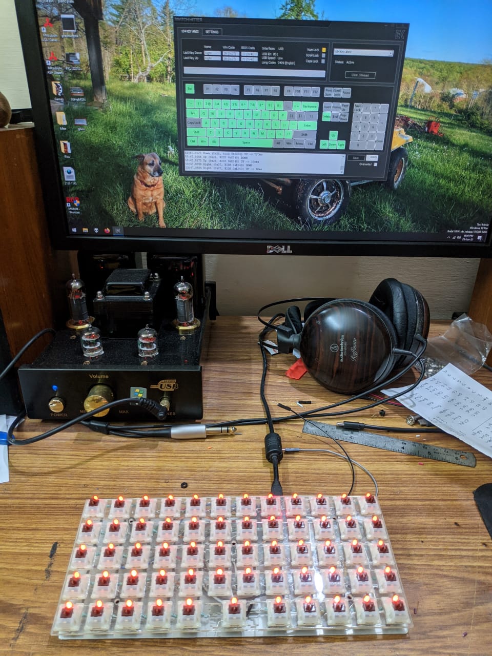
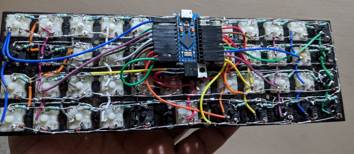
Pro Micro's been flashed and soldered! The keyboard is all done right?
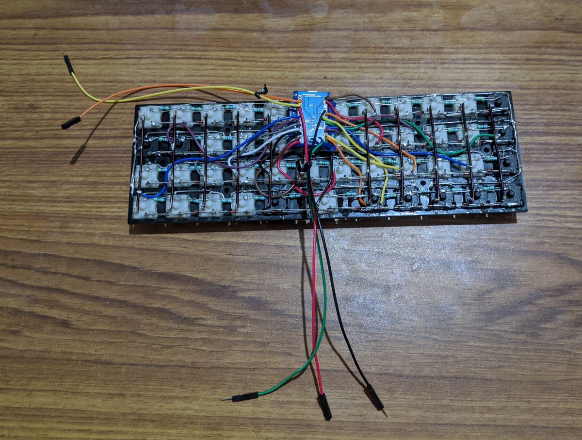
I was in for a rude shock. I faced multiple keys not working, primarily because of the enamelled wires and the difficulty soldering on them. When I thought I had fixed them all, the keys still did not work. Heck, couple of keys didn't work at all.Press some keys, same keys from same row but different column also get activated. Replaced the dead switches, which by themselves were a right pain and I still had problems. I was borrowing the micro USB from my parent's charger so got a differnt cable. Connect it to the pro micro and I get a warning which says USB power exceeded! Now, one of the ICs on the pro micro is getting ridiculously hot, change back to the original cable and still no change. Pro micro is dead.
What the **** is happening here?
I then took some time off. I gave more thought on how I have built the diode array for the rows. I realised how I had messed up with the circuitry - no wonder the keys wouldn't work. I took a deep look into the LED backlight array and it was clear I had screwed up on that front too. Dammit.
Kept the keyboard aside and took a break.
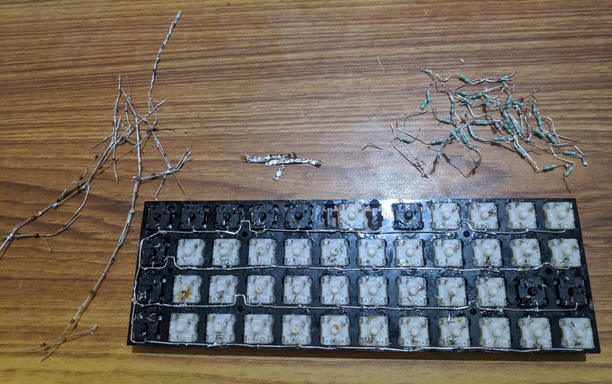
This is when I decided to start from scratch.
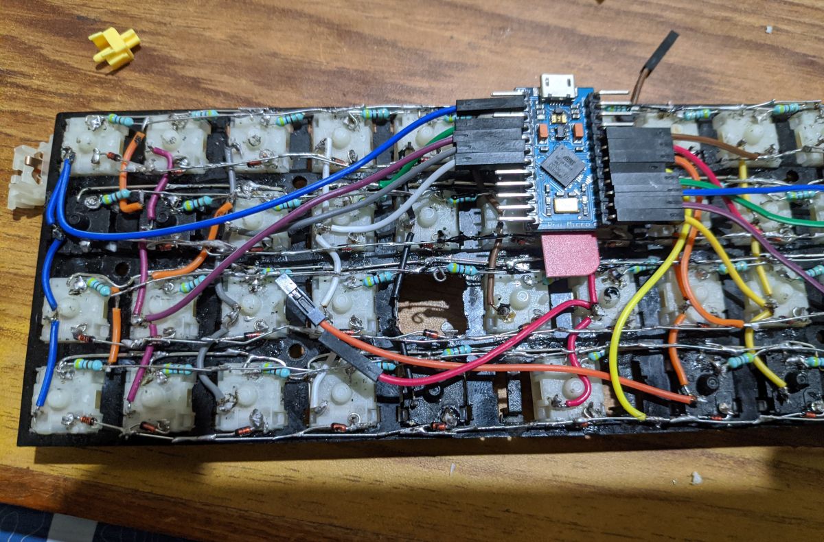
First step for the second attempt was take off all sketchy or problematic circuits. Removed the enamelled wires, diode array and the LED resistor array too. I retained the negative array for the backlight because apparently that is the only one good thing I did in my first attempt. Ugh.
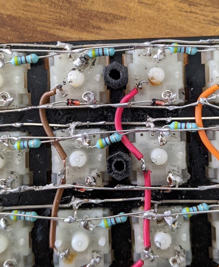
Next wa the reistor array for the backlighting. I found soldering one leg into each LED leg then jopining them together worked better. They were slightly wider than the earlier attempt but hey this time its been soldered right.
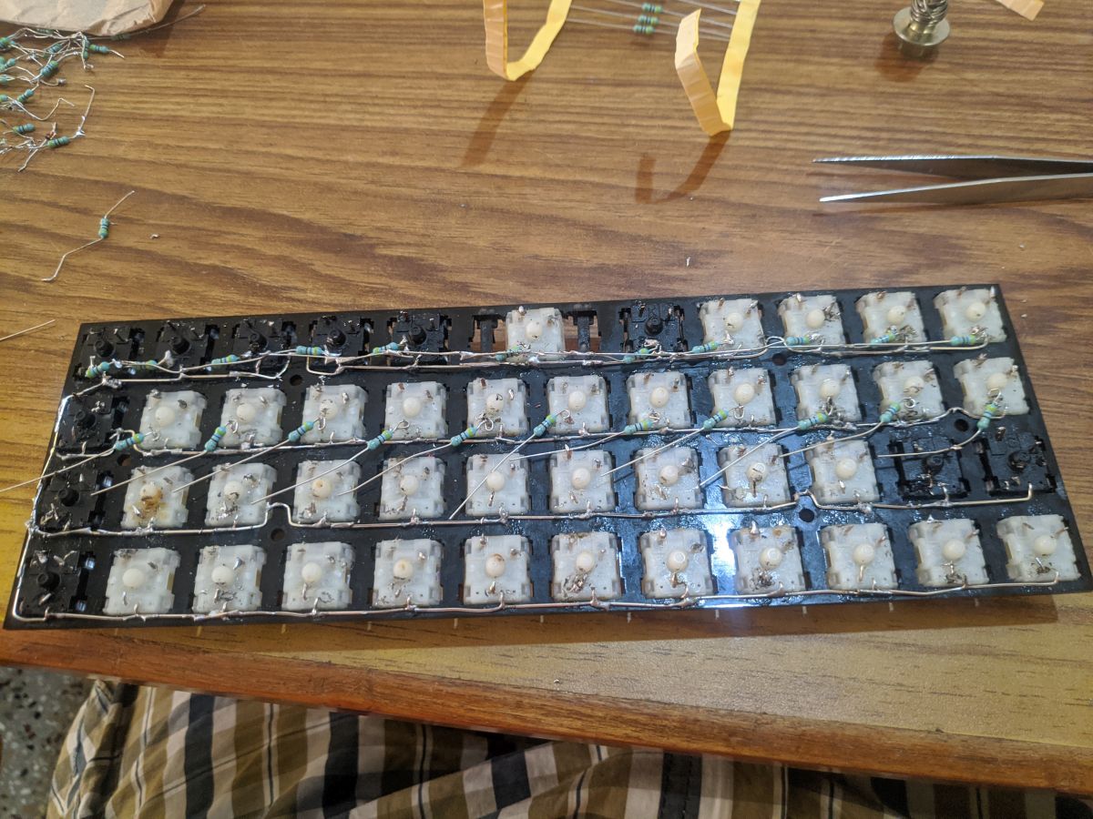

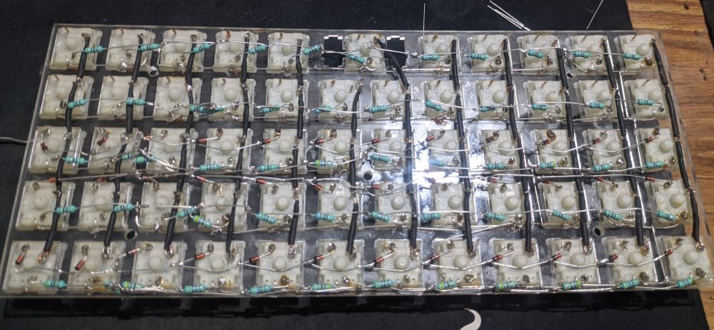
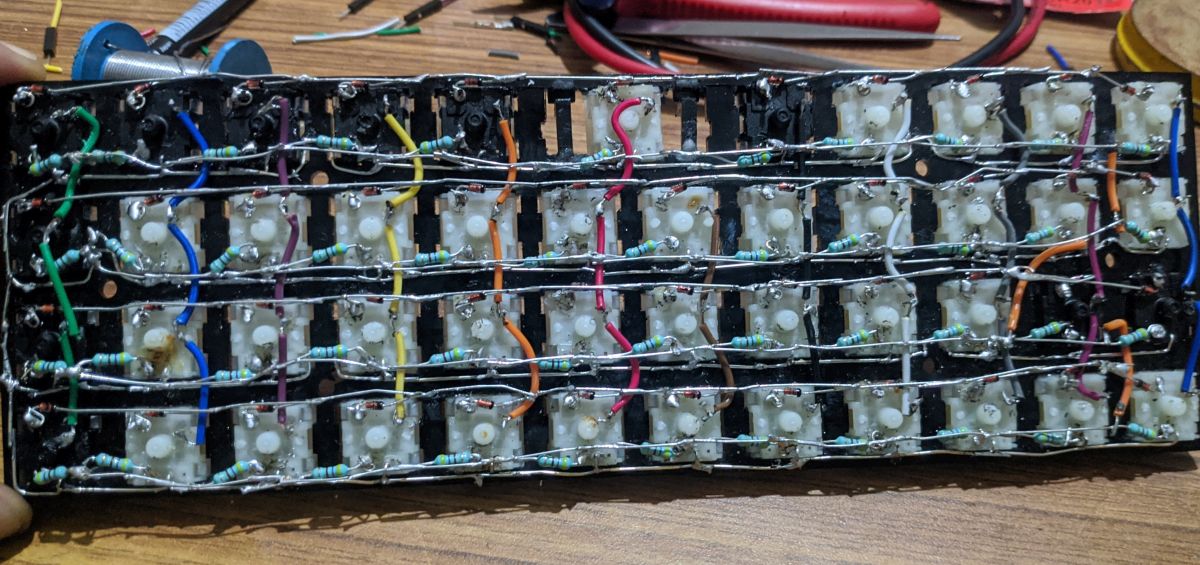
Next was the diode row array. Funnily enough, I used the same principle for the diode array as it was similar.
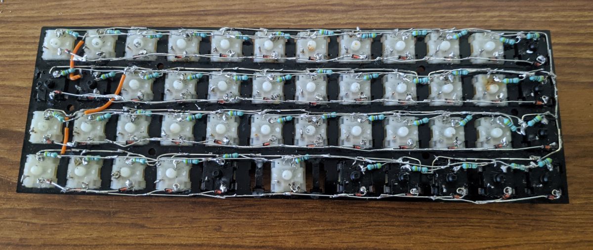
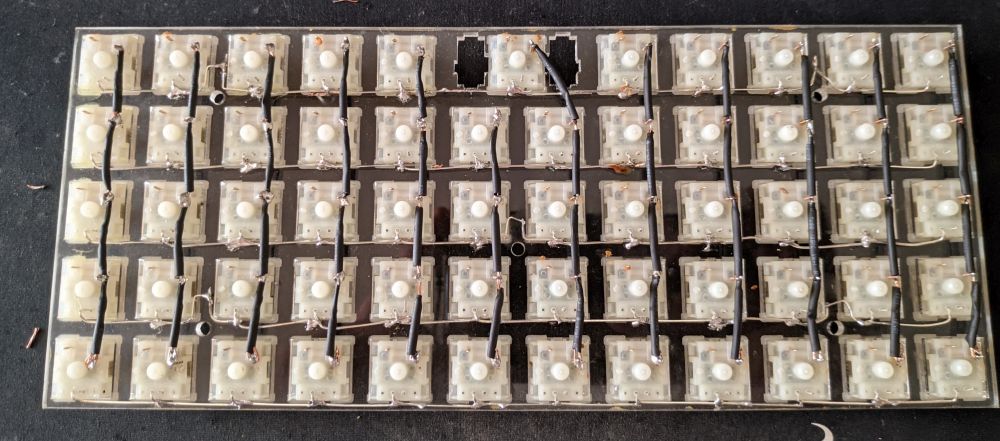
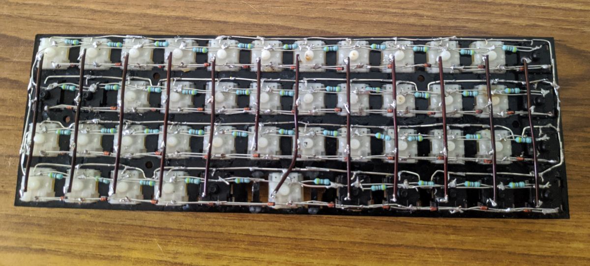
Last item on the agenda was to solder back the the columns. I went for regular jumper wires and they worked really well, as they had done with my previous handwired keyboard.
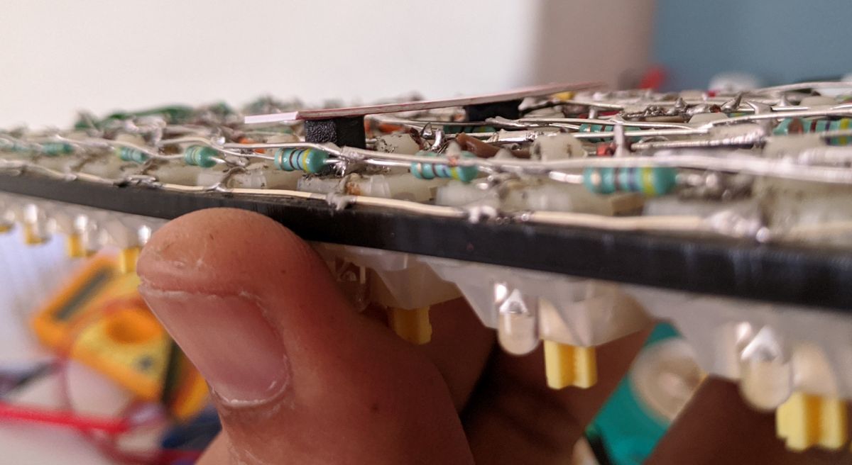
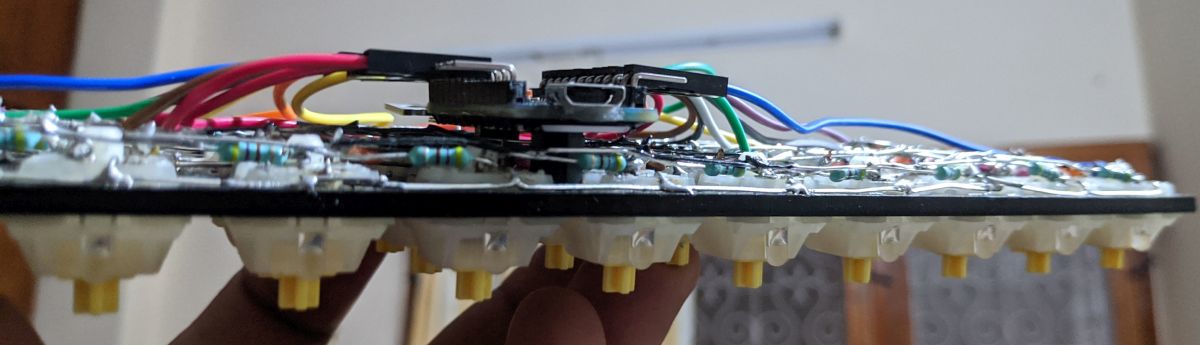
With the main array done, the focus was on how to solder and fix the pro micro to the keyboard while not disturbing any wires or solder connections underneath. I had to mount the pro micro onto the keyboard rigidly but without it having touching the circuit underneath.
I found the solution with a 6mm nylon M3 spacer I had lying around. This was the perfect height to prop up the pro micro! So I fevi quikked two of them in the center
I next needed a rigid piece which can be fixed to the standoffs and to which I can fix the pro micro. I had 3mm acrylic pieces but they would just add to the thichness of the keybopard. I found the answer thanks to Mukesh bhai.
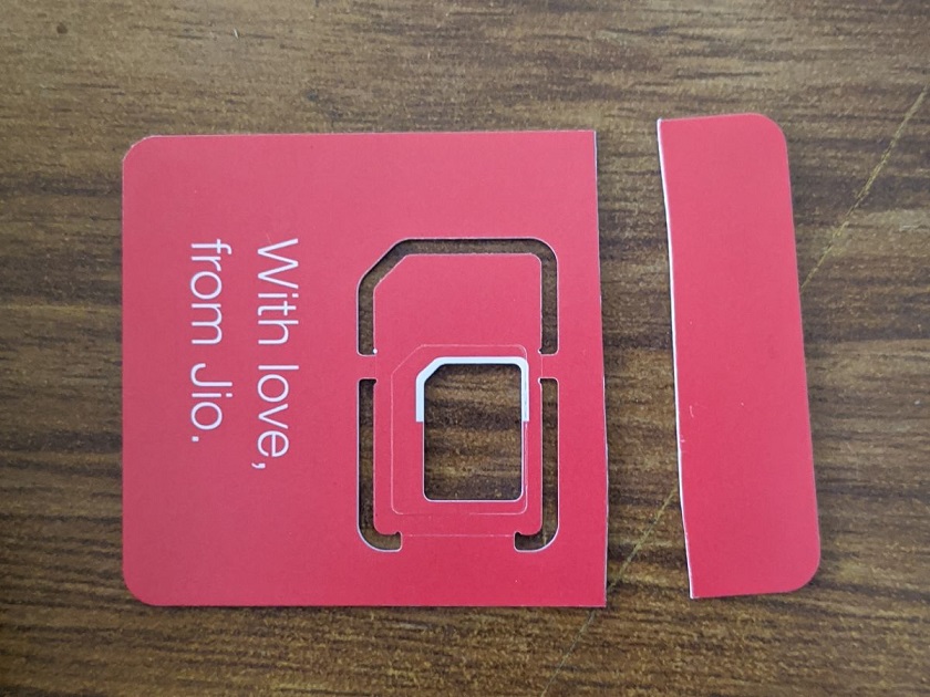
Cut a strip off and glue it again to the top of the standoffs. Woohoo they now clear everything!
Thankfully I had one spare pro micro lying around. I did not want to screw it up and so I bought some right angle connectors, soldered them on the pro micro, bought another set of ribbon cables, soldred the column/row/backlight wires while making sure I retain a connector in each of them. Incase the pro micro had to come off.
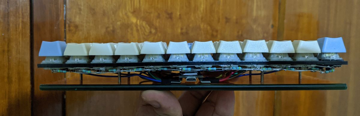
I gotta admit - the end result is solid but too thick. But hey, it works right?
WRONG. one switch is now dead and needs swapping out. Urggggh. This wasn't the case before and why did it have to die now?
Oh well the show must go on. Took out the switch
...and soldered a new one on.
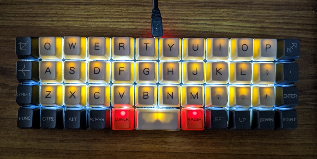
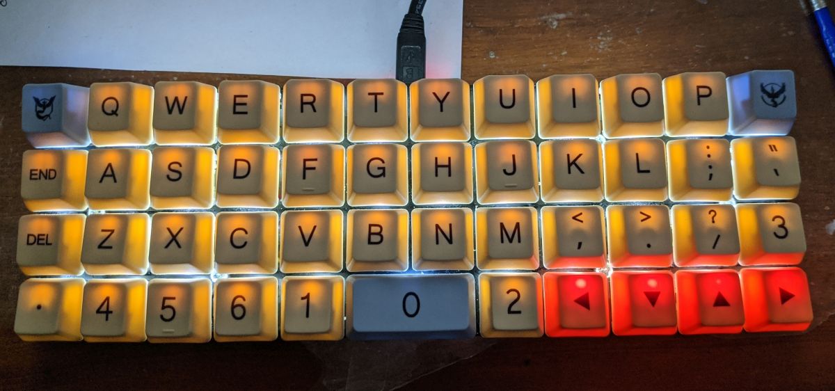
Does it work? Yes! Finally, all keys work!
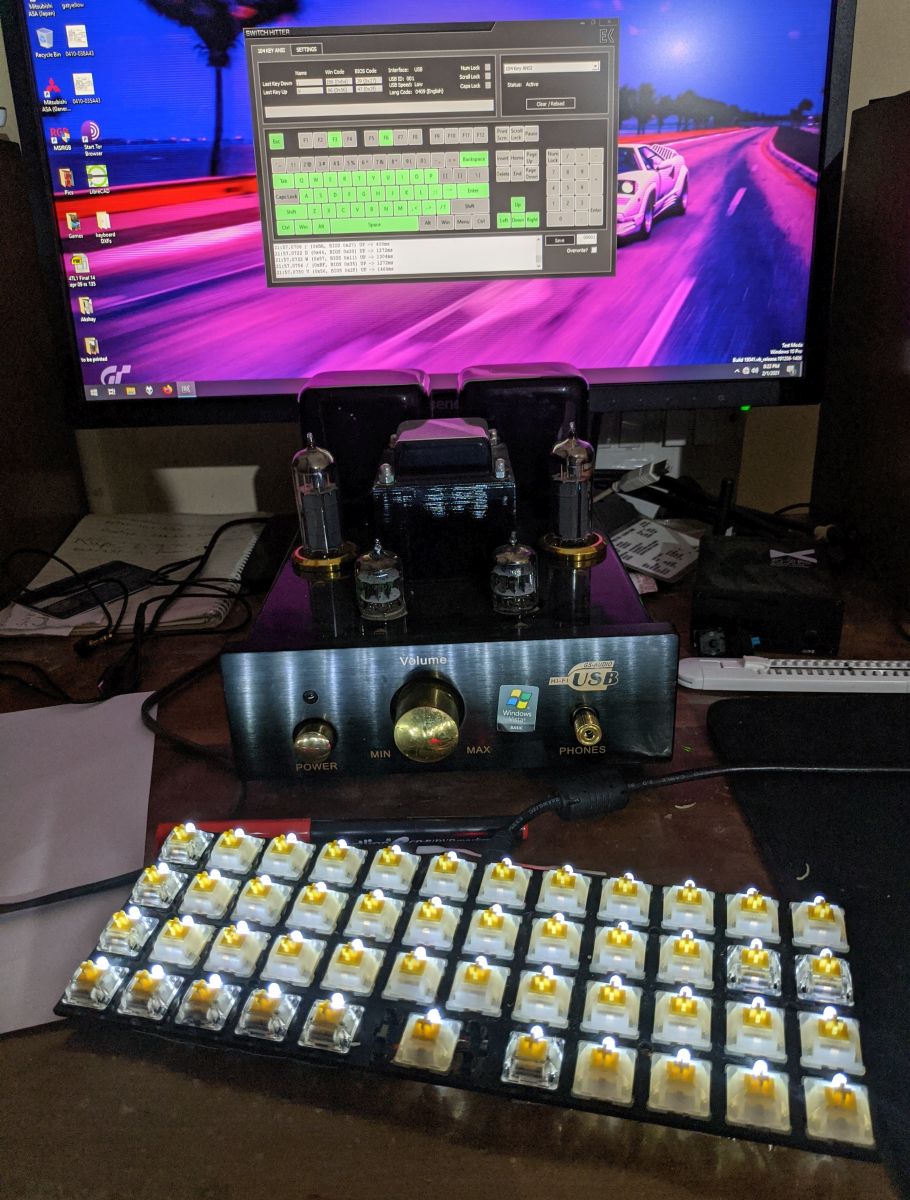
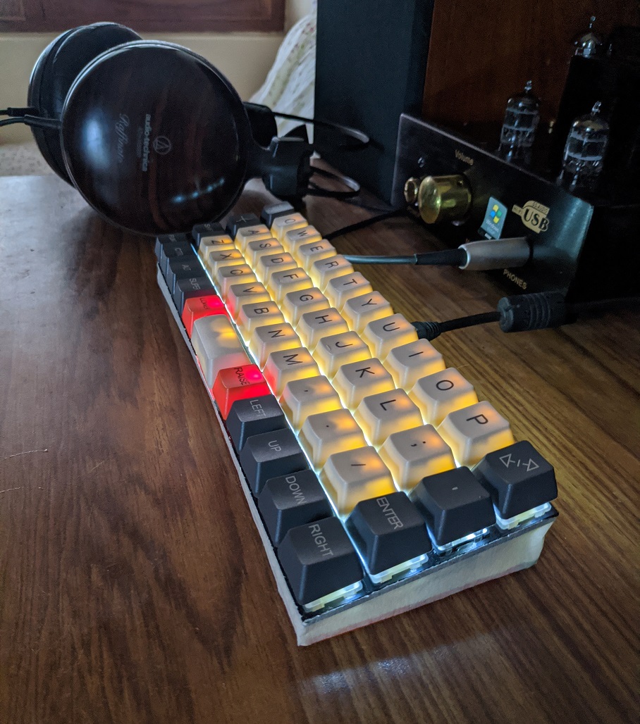
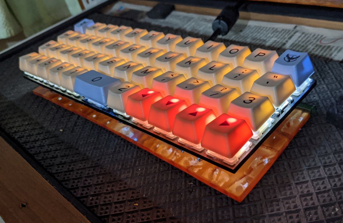
My god the backlight is so strong, I look into the keyboard for couple of seconds without keycaps and I am temporarily blinded for a few seconds. Thankfully the backlight control works and I can adjust the brightness.
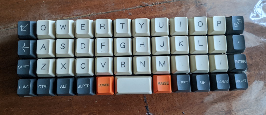
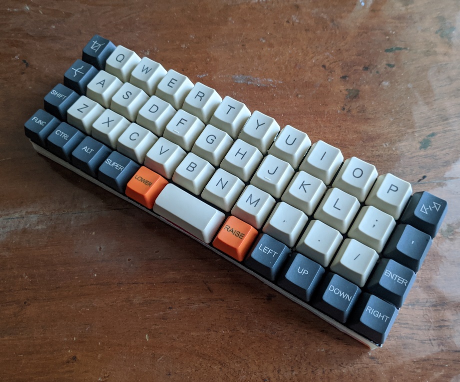
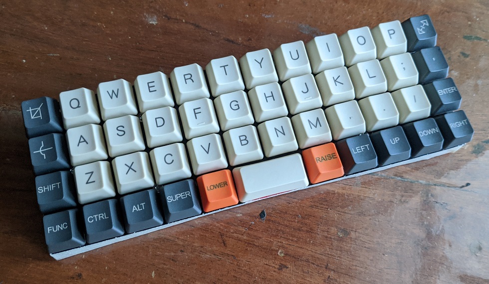
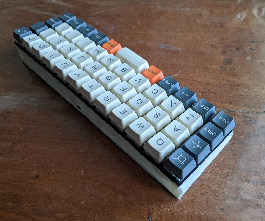
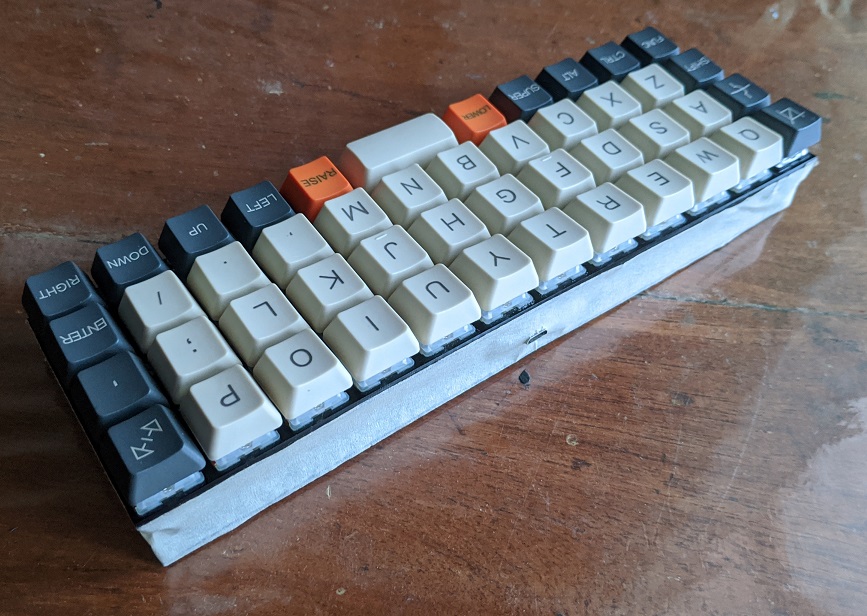
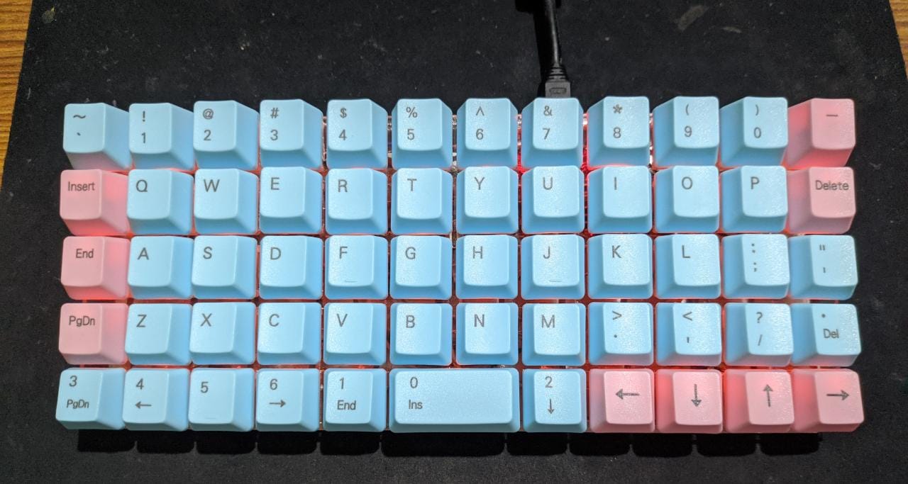
Add a set of keycaps, screw in the base and I'm done. Phew. Hey it looks good though!
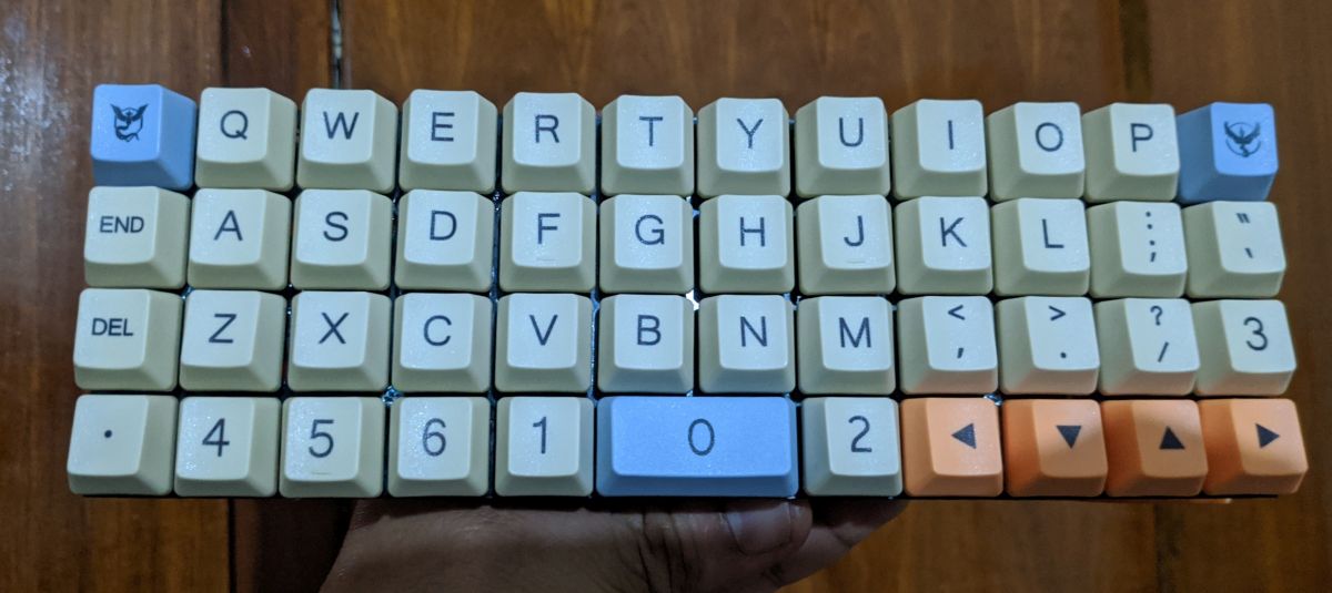
The standoffs I used for the base were juust right.
These keycaps aren't doubleshot/allow backlighting but they still looked decent.
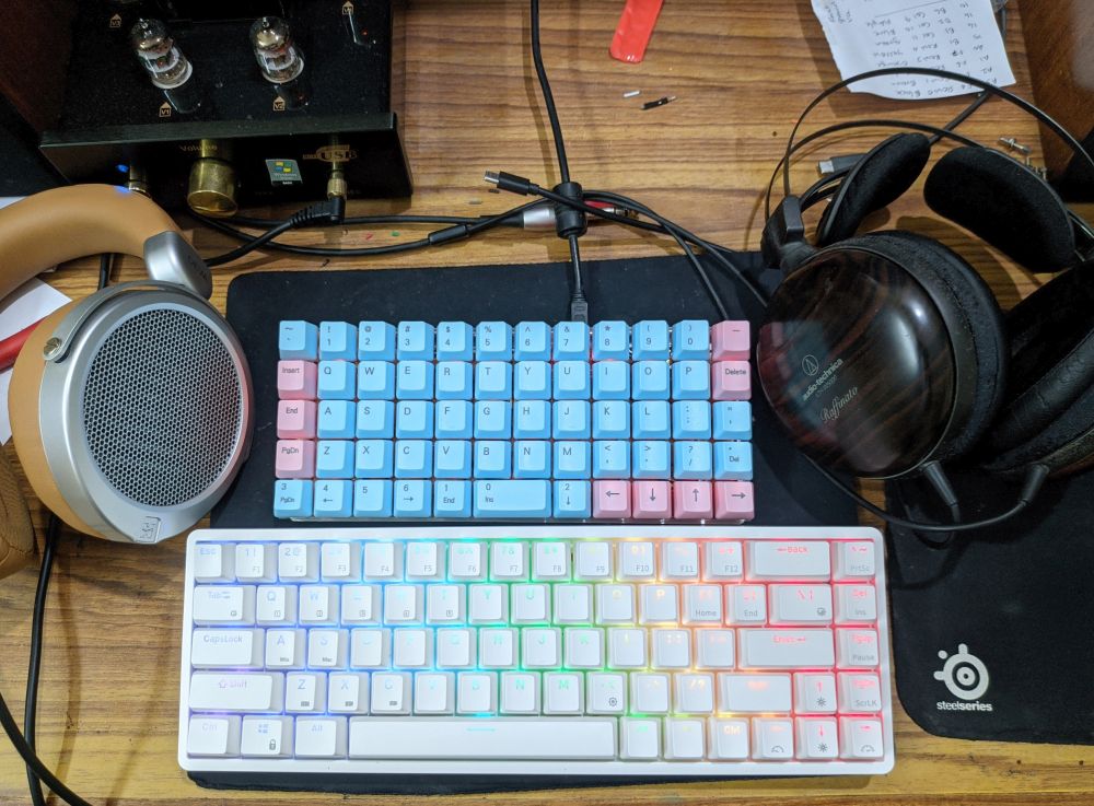
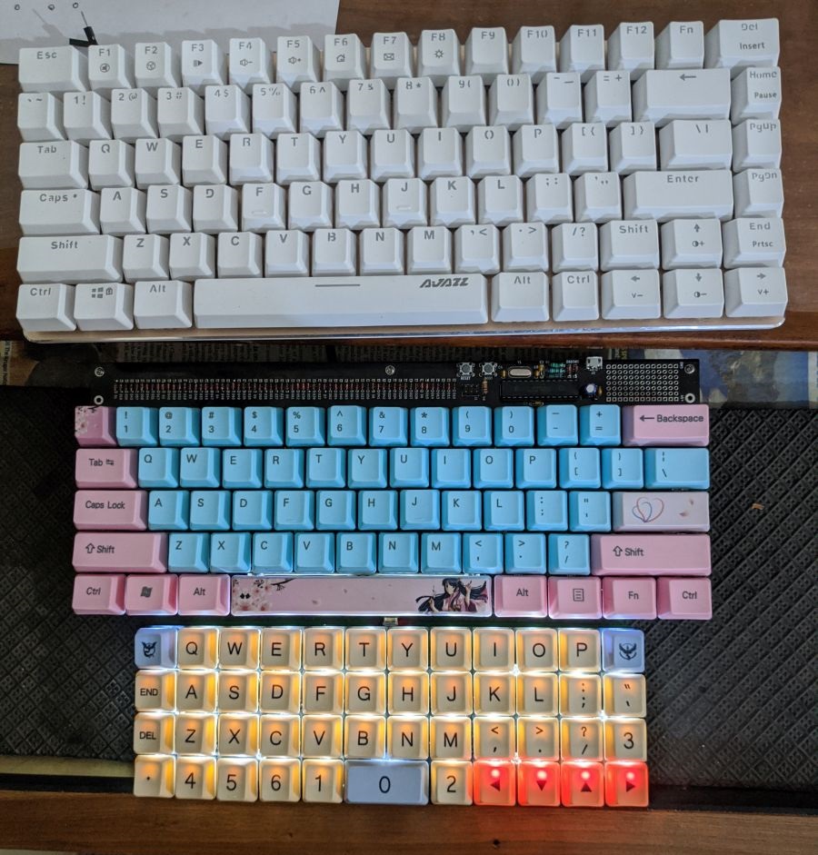
Finally, all my custom keyboards - Handwired Ajazz AK33, Tartan 60% and the Planck in decreasing order of size.
I finished this keyboard in the last week of january, why am I posting the log only now? The truth is, shifting to a small ortholinear keyboard was ridiculously difficult for me and I am not even a touch typist. I used the Planck on and off in the first month with the Tartan being used for over 90% of the time. I struggled a LOT whenever I had to input number or passwords.
One of the days, dad managed to hose down the PC. Don't ask me how. The tartan got completely soaked and so I replaced it with the Planck. By this time I had decided to stick with the Planck and see how it goes. Two weeks down, I am pretty comfortable with this keyboard now and it feels good. In fact I have typed this whole log exclusively on the Planck! This keyboard was a major pain to make but it taught me a lot of things on building keyboards and I am more wiser, which by itself is worth as far as I'm concerned.
I had the initial reservation that anything less than a full size keyboard with 104 keys or at the worst case, a TKL is just a gimmick. It just looks good and saves space while not offering any benefits. Oh how wrong was I.
This is when I bought an Ajazz AK33. A compact keyboard with almost all keys as of a TKL. It was great!
I then attempted to swap out the switches with Gateron Yellows and I ended up killing the keyboard. Danggit.
Fast forward couple of months and I got myself a Tartan 60% keyboard kit. I was still reeling with the loss of the Ajazz so I got most of the components soldered onto the PCB before I received it. I got the kit, assembled and soldered in the switches. The keyboard felt great! The lack of arrow keys was a bit irritating to begin with but I got adjusted to using layers.
Once I found some confidence in soldering keyboards, I attempted to resurrect the broken Ajazz by doing a handwired build. I bought a bunch of diodes locally and arduino Pro Micros from BM-ES. Each cost 345rs and they had free shipping for orders over 1000rs. So I ended up purchasing 3 of them instead of one to save on shipping! Penny wise pound foolish eh? . It went surprisingly well and everything worked on the first attempt!
Wow, who knew handwiring a keyboard will be so easy? (or so I thought...read more to find out)
So, one of the pro micros was used up on the Ajazz and I was left with two more. This gave me an idea to make more handwired keyboards. But what should I do next?
The answer came with this video
This made a lot of sense to me. By this time, I had got pretty used to the Tartan and its layers, so much so that I was not missing the arrow keys by much. The decision was taken - my next keyboard would be a Planck.
As always, the first step to making a handwired keyboard is to make a plate. I first wanted to go with a brass switch plate however it was incredibly difficult to get someone with a laser cutter and would be able to cut metal.
After looking around fior a while, I gave up. Next best option was to get an acrylic plate done. I found another person who wanted a custom keyboard cut out of acrylic, we bundled our orders together. Soon, the laser cutter got laser cutting
Soon, I have a few blank planck switchplates to play with!
Next step was to prepare switches - I went with a combination of Gateron Milky Yellow and Clear Yellow switches. As usual, the switches were opened up for lubing
Fixed a pair of costar stabilisers and temporary stands
Now, for the case. My plan is to do a wooden case for it. However that would take time. Coincidentally, I found a scrap piece of acrylic which was almost the same size as the planck!
Lil' bit of chopping on the sides, mark and tap holes for standoffs. The base is ready.
Yup they fit. looks half decent too
Switches added and glued on so they don't pop back out
Next step was to add the backlight. Yay it works!
Next was soldering diodes to the rows. I've been trying to keep the soldered lines very compact and I think I've been doing a good job at it!
For the columns, I wanted to try something different and use enamelled wire. The enamelled wire are used for motor and transformer coils; unfortunately I had the thickest ones arund 1.1mm thick. I had to file off the enamel to make electrical contact too.
Soldering those thick enamelled wires was pure T O R T U R E. This clearly was a bad idea. But hey, they look good!
Pro Micro's been flashed and soldered! The keyboard is all done right?
I was in for a rude shock. I faced multiple keys not working, primarily because of the enamelled wires and the difficulty soldering on them. When I thought I had fixed them all, the keys still did not work. Heck, couple of keys didn't work at all.Press some keys, same keys from same row but different column also get activated. Replaced the dead switches, which by themselves were a right pain and I still had problems. I was borrowing the micro USB from my parent's charger so got a differnt cable. Connect it to the pro micro and I get a warning which says USB power exceeded! Now, one of the ICs on the pro micro is getting ridiculously hot, change back to the original cable and still no change. Pro micro is dead.
What the **** is happening here?
I then took some time off. I gave more thought on how I have built the diode array for the rows. I realised how I had messed up with the circuitry - no wonder the keys wouldn't work. I took a deep look into the LED backlight array and it was clear I had screwed up on that front too. Dammit.
Kept the keyboard aside and took a break.
This is when I decided to start from scratch.
First step for the second attempt was take off all sketchy or problematic circuits. Removed the enamelled wires, diode array and the LED resistor array too. I retained the negative array for the backlight because apparently that is the only one good thing I did in my first attempt. Ugh.
Next wa the reistor array for the backlighting. I found soldering one leg into each LED leg then jopining them together worked better. They were slightly wider than the earlier attempt but hey this time its been soldered right.
Next was the diode row array. Funnily enough, I used the same principle for the diode array as it was similar.
Last item on the agenda was to solder back the the columns. I went for regular jumper wires and they worked really well, as they had done with my previous handwired keyboard.
With the main array done, the focus was on how to solder and fix the pro micro to the keyboard while not disturbing any wires or solder connections underneath. I had to mount the pro micro onto the keyboard rigidly but without it having touching the circuit underneath.
I found the solution with a 6mm nylon M3 spacer I had lying around. This was the perfect height to prop up the pro micro! So I fevi quikked two of them in the center
I next needed a rigid piece which can be fixed to the standoffs and to which I can fix the pro micro. I had 3mm acrylic pieces but they would just add to the thichness of the keybopard. I found the answer thanks to Mukesh bhai.
Cut a strip off and glue it again to the top of the standoffs. Woohoo they now clear everything!
Thankfully I had one spare pro micro lying around. I did not want to screw it up and so I bought some right angle connectors, soldered them on the pro micro, bought another set of ribbon cables, soldred the column/row/backlight wires while making sure I retain a connector in each of them. Incase the pro micro had to come off.
I gotta admit - the end result is solid but too thick. But hey, it works right?
WRONG. one switch is now dead and needs swapping out. Urggggh. This wasn't the case before and why did it have to die now?
Oh well the show must go on. Took out the switch
...and soldered a new one on.
Does it work? Yes! Finally, all keys work!
My god the backlight is so strong, I look into the keyboard for couple of seconds without keycaps and I am temporarily blinded for a few seconds. Thankfully the backlight control works and I can adjust the brightness.
Add a set of keycaps, screw in the base and I'm done. Phew. Hey it looks good though!
The standoffs I used for the base were juust right.
These keycaps aren't doubleshot/allow backlighting but they still looked decent.
Finally, all my custom keyboards - Handwired Ajazz AK33, Tartan 60% and the Planck in decreasing order of size.
I finished this keyboard in the last week of january, why am I posting the log only now? The truth is, shifting to a small ortholinear keyboard was ridiculously difficult for me and I am not even a touch typist. I used the Planck on and off in the first month with the Tartan being used for over 90% of the time. I struggled a LOT whenever I had to input number or passwords.
One of the days, dad managed to hose down the PC. Don't ask me how. The tartan got completely soaked and so I replaced it with the Planck. By this time I had decided to stick with the Planck and see how it goes. Two weeks down, I am pretty comfortable with this keyboard now and it feels good. In fact I have typed this whole log exclusively on the Planck! This keyboard was a major pain to make but it taught me a lot of things on building keyboards and I am more wiser, which by itself is worth as far as I'm concerned.