
badwhitevision
Disciple
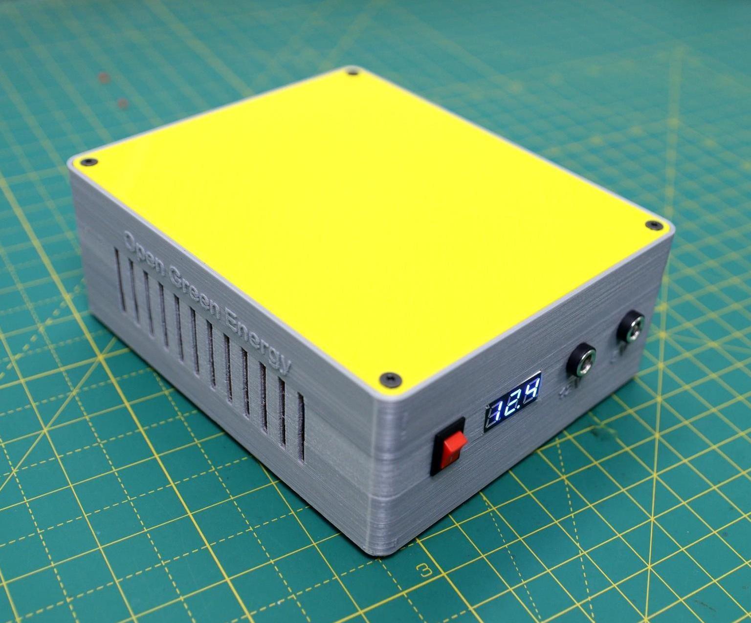
I didn't take pictures or document this build propely. So it is only a wall of text below. If you need more clarity on anything, I shall try to provide it to the best of my abilities.
This is mostly tidbits of information that I learnt along the way that I want to store on the internet because I will forget.
Why?
My HomeLab runs on an old HP Laptop. Laptop has a battery, so can handle power loss. However my media library is on a 3.5 inch HDD which is powered by an external 12V adapter and hence can't handle power loss. This results in a weird situation where I will be able to access Jellyfin but not play anything on it.
How?
This guide - Copied it as is and only changed a few things.
 www.instructables.com
What did I use:
BMS - https://robu.in/product/3s-12v-25a-...ge-current-short-circuit-protection-function/

Why BMS and why this BMS?
A BMS - Battery Management System helps keep your Li-ion cells safe. It prevents overcharging and over discharging by cutting off the load/charge. You always choose a BMS based on the number of cells that you are planning to connect in series and the maximum load it can handle.
This specific BMS because it features load balancing between each series cell.
Why is this important?
Even if you use cells from the same batch, there are bound to be differences between 2 cells and this can at times lead to one cell taking more time to charge than the other. When you attempt to charge such cells, the circuit might cut off when the first cell reaches 4.2V or when the last cell reaches 4.2V. In either case, this can lead to overcharging/undercharging of a cell. By using a load balancing charger, we are eliminating this. This is because the load balancing charger passes current through a resistor and waits until all cells have been charged fully.
Atleast this is my understanding and I am happy to be corrected if I am wrong.
18650 Cells - https://robu.in/product/bak-nmc-18650-2600mah-3c-lithium-ion-3-6v-battery/

BAK 3C Discharge rate 18650 cells.
First time buying Li-ion cells online. Usually I use old discarded PowerBank cells, but I've run out of supply of those.
They appear to be legit. I built mine in a 3S 2P configuration.
MOSFET -
Using a MOSFET here to switch between Mains and battery power. The Gate is connected to the power source and once there is no voltage across the gate, the MOSFET opens up the source and allows it pass to the drain (Battery to Boost converter)

The IRF540N is a N Channel MOSFET, meaning when voltage is present across the gate, it is closed. If voltage is absent, it opens (allows current to flow through).
Boost/Buck and Buck-Boost Converters:
What are these?
Buck converters take a voltage that is higher and convert it to a lower voltage efficiently. Examples - XL4015 and LM2596
Boost converters take a voltage that is lower and convert it to a higher voltage efficiently. Examples - XL6009 and XL6019.
Buck Boost converters take a voltage and are able to manipulate it to a higher or lower voltage efficiently.
My original idea was to use a boost converter at the output (XL6009) such that when the 3S pack goes below 12V, it is still able to supply 12V at the output.
However, the XL 6009 was unable to supply the required start up current for the HDD and kept failing. I assumed that the startup current would be less than 4A (max output of the XL6009) but it appears to not be the case.
So instead, I used one of these modules - https://robu.in/product/solar-wind-energy-charging-cc-cv-power-supply-module/

They are designed to be used to charge batteries with a constant current and constant voltage but they are very bad at it. (Will explain below)
Since these are buck boost converters, I set the voltage output to around 12.2V. This means that a fully charged battery will have it's voltage stepped down (12.6 to 12.2) and an almost discharged battery will have it's voltage stepped up (8.1 to 12.2V)
ALSO - If you are wondering about the 3 POTs on the module, this is what they do and here's how you control them (Took me a long time to figure this out. And the internet is wrong)
1st POT that is closest to the INPUT side is responsible for setting the voltage.
2nd POT is for lighting up a blue LED that lets you know when charging is complete.
3rd POT (closest to the output side) is for setting the constant current value.
To set the Voltage (1st POT), put your multimeter in DC voltage and measure at the output.
To set the Current (3rd POT), put your multimeter in DC current and short the output with the multimeter leads. (2 red LEDs will glow. This is normal and intended)
To set the Charging completed status (2nd POT), set your required current and then choose a load that consumes only the current you would like to flow when charging is completed. Connect this load to the module and then turn the POT until a blue/green LED lights up. This Pot acts as a percentage (1-100%) of the constant current)
You got confused didn't you? Because I did.
Here's an example, I want my cells to charge at 2A. This is my constant current (CC) value.
I want the module to blink blue or indicate charging is done when 60mA current (3% of CC) flows through the load. To do this, I first set the CC (3rd POT) to 2A. Then I connect a load, (say a white LED) that consumes 60mA current. Now, I turn the 2nd POT until the blue LED glows. This indicates charging is completed.
Most Online manuals and guides state that blue is charging and red is charged.
They are WRONG.
DO NOT USE THESE MODULES TO CHARGE YOUR 18650 CELLS in a permanent setup (or any other cells for that matter)
Why?
When this module is powered up, it takes a few milliseconds to set it's output current only after which the load should be connected. If you fail to do this and the load is connected directly to the module as it is being powered, the module tends to go haywire and push large voltages through the load. This is obviously bad and downright dangerous for 18650 cells.
You might ask me, if that is the case, why am I using it for powering the HDD, this is because the module is always powered on. Either by the mains voltage or from the battery. Hence it is safe to state that this is not an issue.
I was initially supposed to use these to charge my 18650 pack, by setting input voltage to a constant 12.65V and current to 500mA. But ever since I observed this behaviour, I had to improvise.
For charging my 3S pack, I decided to use an XL4015 CC CV module. I had to use these since other boost converters were way more expensive.
But this brings with it it's own set of problems. The XL4015 is a buck converter. ie.) It takes a higher voltage and converts it to a lower one. It cannot step up or increase the voltage. This meant that my power supply should be able to supply more than 12.6 V. However this was not the case with my supply.
Hence my ingenious idea to use a buck - boost converter before the buck converter and increase the supply voltage to 13.1V. My charging current was anyway set to a low 500mA, so I wasn't particularly worried about blowing something up.
This allows me to plug in any voltage below 30V and as long as it can supply the required current, the batteries will be charged and the HDD will be powered.
If you've read through this messy and unorganised wall of text, congratulations, you have more patience than me.
Regards,
badwhitevision
This is mostly tidbits of information that I learnt along the way that I want to store on the internet because I will forget.
Why?
My HomeLab runs on an old HP Laptop. Laptop has a battery, so can handle power loss. However my media library is on a 3.5 inch HDD which is powered by an external 12V adapter and hence can't handle power loss. This results in a weird situation where I will be able to access Jellyfin but not play anything on it.
How?
This guide - Copied it as is and only changed a few things.
DIY Mini UPS for WiFi Router V5.0
DIY Mini UPS for WiFi Router V5.0: The pandemic COVID-19 outbreak forced companies to continue with work-from-home policy to maintain social distancing and for business continuity. More and more of us are working from home these days, and that means your home's WiFi networks are more…
What did I use:
BMS - https://robu.in/product/3s-12v-25a-...ge-current-short-circuit-protection-function/
Why BMS and why this BMS?
A BMS - Battery Management System helps keep your Li-ion cells safe. It prevents overcharging and over discharging by cutting off the load/charge. You always choose a BMS based on the number of cells that you are planning to connect in series and the maximum load it can handle.
This specific BMS because it features load balancing between each series cell.
Why is this important?
Even if you use cells from the same batch, there are bound to be differences between 2 cells and this can at times lead to one cell taking more time to charge than the other. When you attempt to charge such cells, the circuit might cut off when the first cell reaches 4.2V or when the last cell reaches 4.2V. In either case, this can lead to overcharging/undercharging of a cell. By using a load balancing charger, we are eliminating this. This is because the load balancing charger passes current through a resistor and waits until all cells have been charged fully.
Atleast this is my understanding and I am happy to be corrected if I am wrong.
18650 Cells - https://robu.in/product/bak-nmc-18650-2600mah-3c-lithium-ion-3-6v-battery/
BAK 3C Discharge rate 18650 cells.
First time buying Li-ion cells online. Usually I use old discarded PowerBank cells, but I've run out of supply of those.
They appear to be legit. I built mine in a 3S 2P configuration.
MOSFET -
Using a MOSFET here to switch between Mains and battery power. The Gate is connected to the power source and once there is no voltage across the gate, the MOSFET opens up the source and allows it pass to the drain (Battery to Boost converter)
The IRF540N is a N Channel MOSFET, meaning when voltage is present across the gate, it is closed. If voltage is absent, it opens (allows current to flow through).
Boost/Buck and Buck-Boost Converters:
What are these?
Buck converters take a voltage that is higher and convert it to a lower voltage efficiently. Examples - XL4015 and LM2596
Boost converters take a voltage that is lower and convert it to a higher voltage efficiently. Examples - XL6009 and XL6019.
Buck Boost converters take a voltage and are able to manipulate it to a higher or lower voltage efficiently.
My original idea was to use a boost converter at the output (XL6009) such that when the 3S pack goes below 12V, it is still able to supply 12V at the output.
However, the XL 6009 was unable to supply the required start up current for the HDD and kept failing. I assumed that the startup current would be less than 4A (max output of the XL6009) but it appears to not be the case.
So instead, I used one of these modules - https://robu.in/product/solar-wind-energy-charging-cc-cv-power-supply-module/
They are designed to be used to charge batteries with a constant current and constant voltage but they are very bad at it. (Will explain below)
Since these are buck boost converters, I set the voltage output to around 12.2V. This means that a fully charged battery will have it's voltage stepped down (12.6 to 12.2) and an almost discharged battery will have it's voltage stepped up (8.1 to 12.2V)
ALSO - If you are wondering about the 3 POTs on the module, this is what they do and here's how you control them (Took me a long time to figure this out. And the internet is wrong)
1st POT that is closest to the INPUT side is responsible for setting the voltage.
2nd POT is for lighting up a blue LED that lets you know when charging is complete.
3rd POT (closest to the output side) is for setting the constant current value.
To set the Voltage (1st POT), put your multimeter in DC voltage and measure at the output.
To set the Current (3rd POT), put your multimeter in DC current and short the output with the multimeter leads. (2 red LEDs will glow. This is normal and intended)
To set the Charging completed status (2nd POT), set your required current and then choose a load that consumes only the current you would like to flow when charging is completed. Connect this load to the module and then turn the POT until a blue/green LED lights up. This Pot acts as a percentage (1-100%) of the constant current)
You got confused didn't you? Because I did.
Here's an example, I want my cells to charge at 2A. This is my constant current (CC) value.
I want the module to blink blue or indicate charging is done when 60mA current (3% of CC) flows through the load. To do this, I first set the CC (3rd POT) to 2A. Then I connect a load, (say a white LED) that consumes 60mA current. Now, I turn the 2nd POT until the blue LED glows. This indicates charging is completed.
Most Online manuals and guides state that blue is charging and red is charged.
They are WRONG.
DO NOT USE THESE MODULES TO CHARGE YOUR 18650 CELLS in a permanent setup (or any other cells for that matter)
Why?
When this module is powered up, it takes a few milliseconds to set it's output current only after which the load should be connected. If you fail to do this and the load is connected directly to the module as it is being powered, the module tends to go haywire and push large voltages through the load. This is obviously bad and downright dangerous for 18650 cells.
You might ask me, if that is the case, why am I using it for powering the HDD, this is because the module is always powered on. Either by the mains voltage or from the battery. Hence it is safe to state that this is not an issue.
I was initially supposed to use these to charge my 18650 pack, by setting input voltage to a constant 12.65V and current to 500mA. But ever since I observed this behaviour, I had to improvise.
For charging my 3S pack, I decided to use an XL4015 CC CV module. I had to use these since other boost converters were way more expensive.
But this brings with it it's own set of problems. The XL4015 is a buck converter. ie.) It takes a higher voltage and converts it to a lower one. It cannot step up or increase the voltage. This meant that my power supply should be able to supply more than 12.6 V. However this was not the case with my supply.
Hence my ingenious idea to use a buck - boost converter before the buck converter and increase the supply voltage to 13.1V. My charging current was anyway set to a low 500mA, so I wasn't particularly worried about blowing something up.
This allows me to plug in any voltage below 30V and as long as it can supply the required current, the batteries will be charged and the HDD will be powered.
If you've read through this messy and unorganised wall of text, congratulations, you have more patience than me.
Regards,
badwhitevision
Last edited: