Advanced Electronics Couldn't get info about power IC called UTC8313

chungus

Forerunner
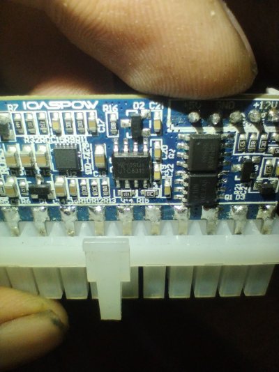
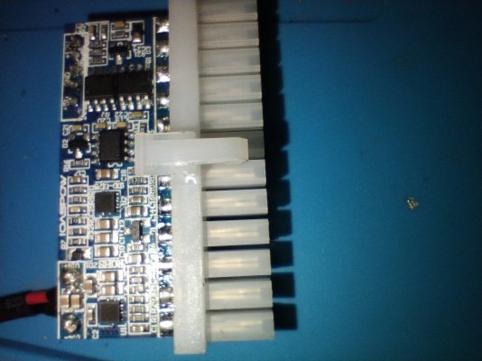
I've recently bought a pico psu from pi+ but after plugging it in it showed 5vsb, but after after some time there's no voltage on 5vsb, I initially thought it might be my motherboard but after changing the motherboard I came to conclusion that something's wrong with pico psu, the controller chip on this PSU is UTC8313 which is connected to 2 mosfets. I couldn't get any data regarding this chip. Chatgpt is giving weird incompatible recommendations which I don't trust. There's no data sheet on this ic as well. I've contacted pi+ also and they are saying that they cannot offer replacement as its already more than 3 days. So I'm stuck here. For some of you curious here's the picture of the chip with two mosfets on the side. Let me know what to do
 

Attachments

  • IMG_20250611_031533913.jpg
    IMG_20250611_031533913.jpg
    353.7 KB · Views: 26
It's the power supply issue, we must get the +5VSB running without anything connected to the picopsu, just turn on the power for picopsu, there should be voltage on the +5VSB pin.

The UTC8313, is probably some chinese chip, not widely known, probably that's why no infromation about this on the net.

I found the pico psu schematic this one is popular and it doesn't use the UTC8313.

It uses ISL6440 which is popular and I am thinking the UTC8313 is an alternative of this.

There is one other small IC WTI751002 which seems to be a Power Management & Supervisor IC. I don't think it has anything to do with the voltage on +5VSB pin

The PSU must have +5VSB already active for it do anything. This means you have check the circuits around the +5VSB.

1749721401235.png


But this schematic is for this picopsu

1749724503590.png

1749724641006.png

1749724652987.png

1749724660931.png

1749724673052.png

1749724685926.png


It seems that schematic is not complete, T3, T4, T5, T6 is missing, one of them might be a 5V regulator, check if you have something like that, 3 pin device, linear regulator.
 
Screenshot_20250612-122256.png
after search I found something similar it's a chip called gr8313 instead utc8313 it seems to have ground pin at same location but I'm getting 12volt at fault protection pin not vcc
 
That is the same monitoring IC as this one.

1749725960631.png


has nothing to do with the +5VSB.

You main controller IC is probably this one.

1749726094560.png


Now the question is where is the +5VSB is getting generated.

1749726220443.png
 
Last edited:
but I'm getting 12volt at fault protection pin not vcc
I see,

Check the voltage on PGI pin it must be higher than 1.2V, the PGI pin checks the voltages on all the rails, it receives a scaled voltage. if voltage is greater than 1.2V all supplies are fine, if it is lower than the FPO pin will have some voltage on it, otherwise it should be low to ground.

The FPO pin is the same as FPOB pin the schematic, if it is high than if will turn off all the output rails, 3.3, 5, 12, but I think it has nothing to do with the, +5VSB.

So probably your output voltages are not on, and this chip is detecting a fault.

And your output voltages might not be ON due to lack of +5VSB.


There are two of them though and I think they are auxiliary chips helping the main one
I see, they the alternatives for the ISL6440 chip mentioned above.

1749727946222.png


Notice it has two identical sides, one is used for 3.3v and the other is for 5.0v, so in your board they used two of them, instead of using this one single type with dual outputs.

They probably found that using those two separately of same types is cheaper than this single one with dual outputs from a reputable company.

I think this is the case here.
 
Last edited:
  • Like
Reactions: chungus
I see,

Check the voltage on PGI pin it must be higher than 1.2V, the PGI pin checks the voltages on all the rails, it receives a scaled voltage. if voltage is greater than 1.2V all supplies are fine, if it is lower than the FPO pin will have some voltage on it, otherwise it should be low to ground.

The FPO pin is the same as FPOB pin the schematic, if it is high than if will turn off all the output rails, 3.3, 5, 12, but I think it has nothing to do with the, +5VSB.

So probably your output voltages are not on, and this chip is detecting a fault.

And your output voltages might not be ON due to lack of +5VSB.


I see, they the alternatives for the ISL6440 chip mentioned above.

View attachment 240013


Notice it has two identical sides, one is used for 3.3v and the other is for 5.0v, so in your board they used two of them, instead of using this one single type with dual outputs.

They probably found that using those two separately of same types is cheaper than this single one with dual outputs from a reputable company.

I think this is the case here.
Yeah, you're right and there's no voltage on pgi or any other pin except for fpo. So there goes my project for making motherboard power consumption meter with this. Now I'm thinking I'll buy a atx female to male extension and join all 12v, 5v, 3.3v rails coming from psu to multiple voltmeter ammeter displays to the motherboard.