rsaeon
Patron
It's been a really long time since I've done any kind of build log, so here we go! As posted in the everyday thread:
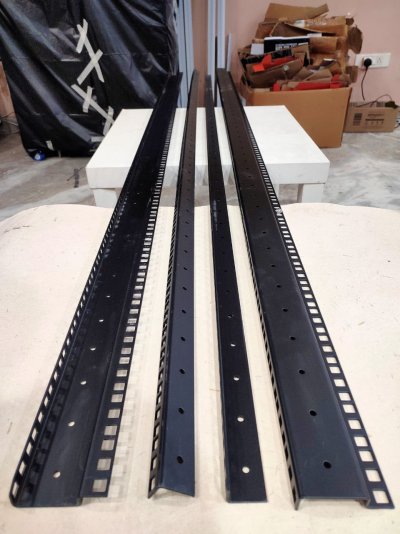
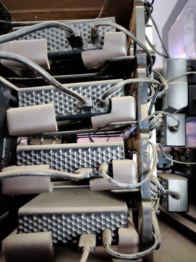
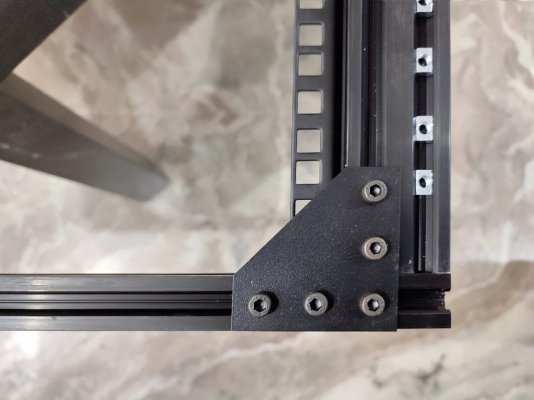
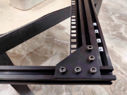
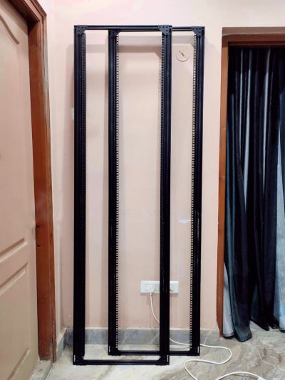
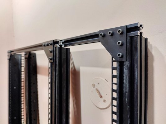
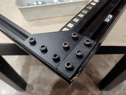
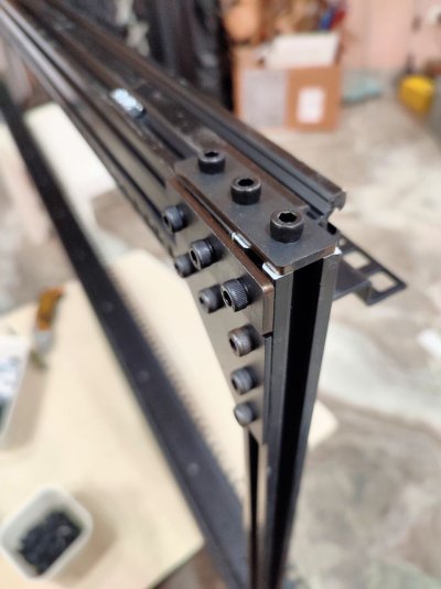
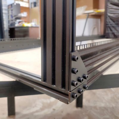
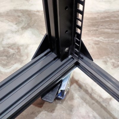
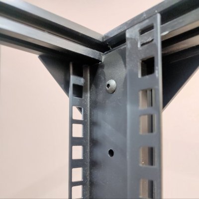
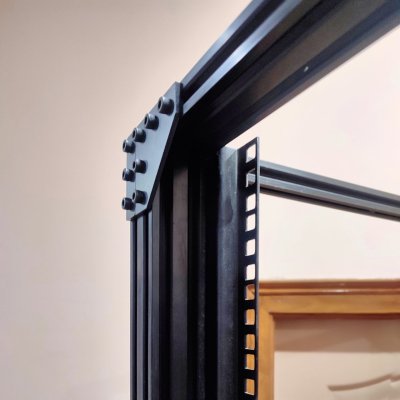
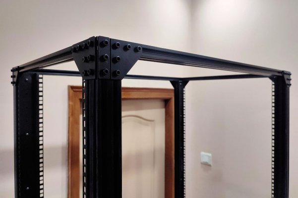
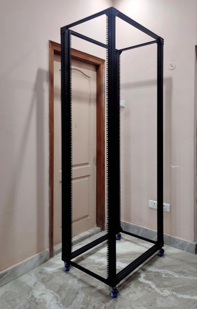
I'm building my own 45U open frame server rack! The frame will be made out of 4040/2060/2040/2020 extrusion, this is actually my second rack. The first is all covered up in the background, since I (temporarily) ran out of budget for that project — that one is "work" related while this one is for personal use.
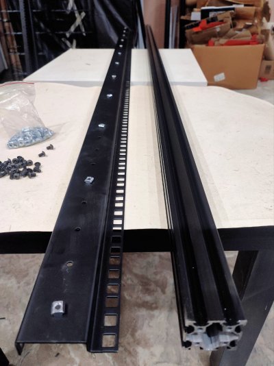
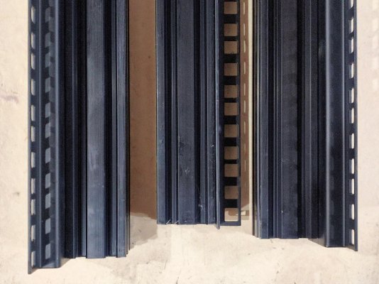
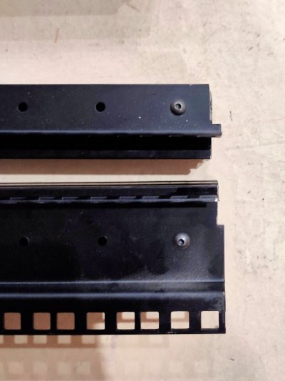
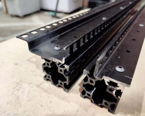
If you want to do something like this, keep in mind that these rails are actually slightly taller than 45U — the double rails are a few mm longer, and the regular rails are twice as much. Buy the rails first, measure them, then buy the extrusion. Maybe I'll make a build log out of this one.
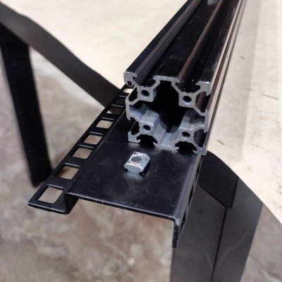
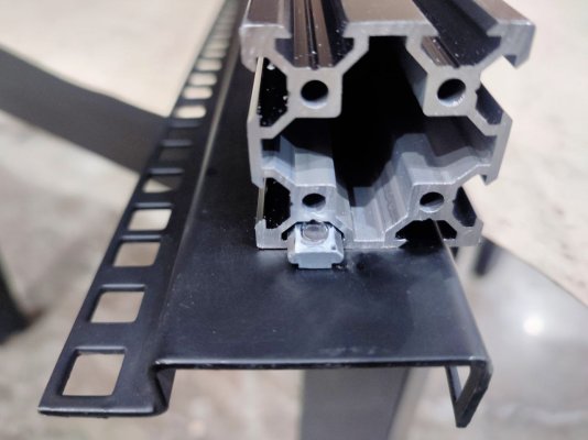
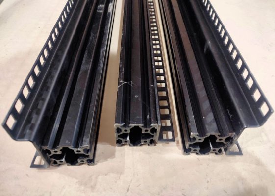
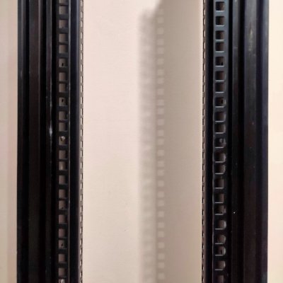
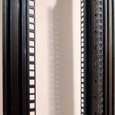
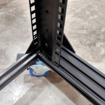
These are from Penn Elcom on Amazon, the double rails will be in the front and the other two in the rear. I probably should've gotten double rails for all four corners since it was like just Rs 100 more per rail. I'm assuming the double rails help with rigidity when mounting equipment that don't extend all the way back and instead have extra mounting points on the sides behind the ears. Or maybe they're for 0U PDU's?
I've never even seen a server rack in person so this is all very exciting for me, I'm loving the high-quality matte black power coating on these — most rack owners probably don't say things like that, haha.
Links to the rails:
https://www.amazon.in/gp/product/B084D4QPGX/
https://www.amazon.in/gp/product/B084D3PH99/
Thank you.
I'm on the top floor and it gets really warm here since we have nothing overhead so I cool down the rooms by having air flow through one corner to the other corner with a few exhaust fans. This helps but it also means a lot more dust than usual, which means a lot more cleaning than usual. I'm intending to have castors under the rack to slide it in and out of the corner for easy sweeping/mopping (I do my own cleaning so nothing is at risk by hired help). I'm not sure if I'll have spinning disks in the rack because people usually advise not having castors on anything with spinning disks. This discussion briefly mentions this:
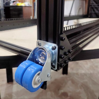
The castors I'm going to be using are these:
https://www.amazon.in/dp/B08CC9441R
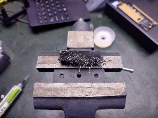
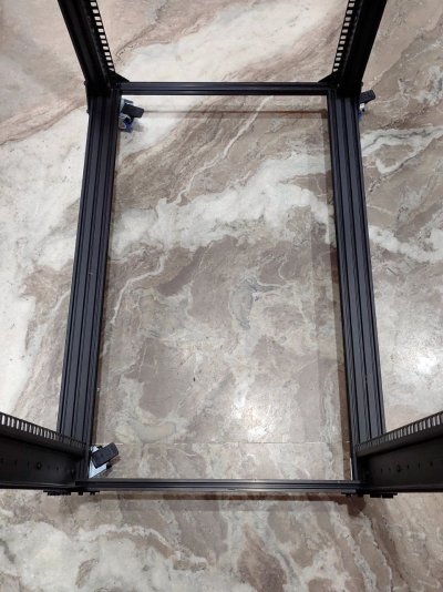
They have 40mm wide mounting hole pattern which is perfect for a 2060 extrusion that I'll use as the base. They're rated for 60kg per castor, so 240kg overall. I'm not intending to use any actual rack mount servers though, there will be a rack mount UPS that's 10KG, a battery pack that's 70KG, and maybe one or two full sized desktops. Maybe a patch panel, a router, a switch or two, and shelf or two holding a few tiny pcs. The 240kg limit might end up being a factor later though I'm not sure how I'll overcome it — the design of the rack in my head is a basically a wireframe cube with castors on the bottom four corners and no solid panels (for now).

I'm building my own 45U open frame server rack! The frame will be made out of 4040/2060/2040/2020 extrusion, this is actually my second rack. The first is all covered up in the background, since I (temporarily) ran out of budget for that project — that one is "work" related while this one is for personal use.
If you want to do something like this, keep in mind that these rails are actually slightly taller than 45U — the double rails are a few mm longer, and the regular rails are twice as much. Buy the rails first, measure them, then buy the extrusion. Maybe I'll make a build log out of this one.
These are from Penn Elcom on Amazon, the double rails will be in the front and the other two in the rear. I probably should've gotten double rails for all four corners since it was like just Rs 100 more per rail. I'm assuming the double rails help with rigidity when mounting equipment that don't extend all the way back and instead have extra mounting points on the sides behind the ears. Or maybe they're for 0U PDU's?
I've never even seen a server rack in person so this is all very exciting for me, I'm loving the high-quality matte black power coating on these — most rack owners probably don't say things like that, haha.
Links to the rails:
https://www.amazon.in/gp/product/B084D4QPGX/
https://www.amazon.in/gp/product/B084D3PH99/
Nice. Some words of advice, pay attention to load bearing capacity, make sure to place it in a pace where you can access the rear if that is required, moving it can be a pain, depending upon the type of rack the screws/hardware can be difficult to find and finally try to think ahead about all the things you want to place in it, sometimes there are things that won't fit. Racks are very practical and to the industrially inclined, beautiful. Good luck with your project.
Thank you.
I'm on the top floor and it gets really warm here since we have nothing overhead so I cool down the rooms by having air flow through one corner to the other corner with a few exhaust fans. This helps but it also means a lot more dust than usual, which means a lot more cleaning than usual. I'm intending to have castors under the rack to slide it in and out of the corner for easy sweeping/mopping (I do my own cleaning so nothing is at risk by hired help). I'm not sure if I'll have spinning disks in the rack because people usually advise not having castors on anything with spinning disks. This discussion briefly mentions this:
The castors I'm going to be using are these:
https://www.amazon.in/dp/B08CC9441R
They have 40mm wide mounting hole pattern which is perfect for a 2060 extrusion that I'll use as the base. They're rated for 60kg per castor, so 240kg overall. I'm not intending to use any actual rack mount servers though, there will be a rack mount UPS that's 10KG, a battery pack that's 70KG, and maybe one or two full sized desktops. Maybe a patch panel, a router, a switch or two, and shelf or two holding a few tiny pcs. The 240kg limit might end up being a factor later though I'm not sure how I'll overcome it — the design of the rack in my head is a basically a wireframe cube with castors on the bottom four corners and no solid panels (for now).
Last edited:


