*** The Anti-Showoff Thread ***

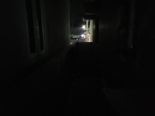
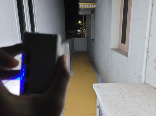
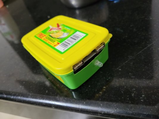
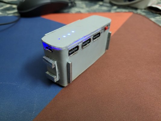
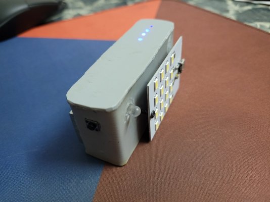
Continuing my diy adventures, today made this mini flashlight with crazy brightness, magnets to stick it anywhere and usb charging.

I needed a flashlight that can attach to metal railings of roof in outdoor room in case of a powercut so made one myself.
 

Attachments

  • 20230312_205911.jpg
    20230312_205911.jpg
    339.9 KB · Views: 257
  • 20230312_205921.jpg
    20230312_205921.jpg
    297.7 KB · Views: 264
  • 20230312_210045.jpg
    20230312_210045.jpg
    52.8 KB · Views: 253
  • 20230312_210103.jpg
    20230312_210103.jpg
    180.1 KB · Views: 272
Continuing my diy adventures, today made this mini flashlight with crazy brightness, magnets to stick it anywhere and usb charging.

I needed a flashlight that can attach to metal railings of roof in outdoor room in case of a powercut so made one myself.
Any video you referred to make it?
 
Not any specific video but got idea to make the case from pvc pipes from some youtube videos. Used single 2600mah 18650, powerbank circuit (to take care of charging, discharging and current protection) and 5v led panel to build it.
I see..I am trying to make one. Just searching for the right video to get proper info, before I mess it up.
Where did you get 18650 batteries btw?
 
I see..I am trying to make one. Just searching for the right video to get proper info, before I mess it up.
I hope you know how to work with li-ion batteries as they are dangerous if handled without proper knowledge. Pm me if you need any ideas/help.
Where did you get 18650 batteries btw?
I got it from makerbazar.com but there are a dozen of sites which sell those. Also if the capacity is above 3000mah or if the price is too low for a 18650 its probably fake so check properly.
 
Oh good luck mate, checkout diyperks youtube channel as he's my inspiration for these kind of stuff. Also found a site which sells board+cable. Pm me if you need any help!
Hello mate, absolutely awesome work on these builds. I'm attempting something similar with my old laptop. Could you point me some sources you used for the hardware or even something to help understand the chipsets involved. I'm pretty noob at electronics so can't figure out a generic part's worth. Any help is appreciated. Keep up the diy awesomeness, you are an absolute inspiration.
 
Hello mate, absolutely awesome work on these builds. I'm attempting something similar with my old laptop. Could you point me some sources you used for the hardware or even something to help understand the chipsets involved. I'm pretty noob at electronics so can't figure out a generic part's worth. Any help is appreciated. Keep up the diy awesomeness, you are an absolute inspiration.
Thank you for your kind words. There are a lot of tutorials on youtube for the same. This one was my guide
but there are many others.

Here are some basics:
Laptop displays need a display driver board to run separately as a monitor. To get the right one first search for your display model number (will usually be on the back of panel) and find its specifications. Resolution, refresh rate, voltage, and type of lvds display cable (older 1366×768 diplays use 40 pin while newer 1080p displays use 30 pin). Then search for the compatible driver board. (which is hard to find sometimes, especially the cable.) Boards are around 1000 rupees. Also some boards have pre-flashed firmware for the specific resolution while some need manual flashing with a pendrive. Thats relatively easy.
Note:
Be careful while removing the display from laptop are you might damage the circuits or flex cables behind the panel.

If you have any more queries pm me.


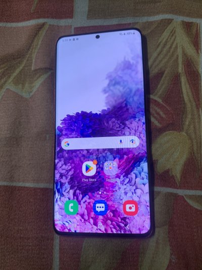
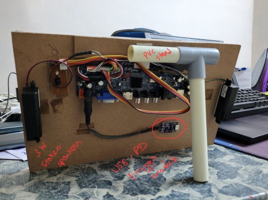
Looks like I need to start a new thread for diy stuff lol. Anyway here's the 'upgraded' monitor with better speakers, a stand and Usb-pd power input.

Also made a 8000mah soap box powerbank:sweatsmile:
 

Attachments

  • 20230430_213037.jpg
    20230430_213037.jpg
    302.2 KB · Views: 212
  • 20230430_213230.jpg
    20230430_213230.jpg
    185.2 KB · Views: 193
Last edited:
Thank you for your kind words. There are a lot of tutorials on youtube for the same. This one was my guide
but there are many others.

Here are some basics:
Laptop displays need a display driver board to run separately as a monitor. To get the right one first search for your display model number (will usually be on the back of panel) and find its specifications. Resolution, refresh rate, voltage, and type of lvds display cable (older 1366×768 diplays use 40 pin while newer 1080p displays use 30 pin). Then search for the compatible driver board. (which is hard to find sometimes, especially the cable.) Boards are around 1000 rupees. Also some boards have pre-flashed firmware for the specific resolution while some need manual flashing with a pendrive. Thats relatively easy.
Note:
Be careful while removing the display from laptop are you might damage the circuits or flex cables behind the panel.

If you have any more queries pm me.


Looks like I need to start a new thread for diy stuff lol. Anyway here's the 'upgraded' monitor with better speakers, a stand and Usb-pd power input.

Also made a 8000mah soap box powerbank:sweatsmile:
That's really helpful as beginner. Don't think I have pm privileges here yet. Didn't know about the firmware flashing, guess I need to do some RnD. I've got the disassembly done, I was kinda expecting to use the existing (lvds?) cable but it's somehow lcd + webcam in one which is very confusing. Currently trying to find the controller board but all searches lead me either aliexpress, ubuy or desertcart which I'm kinda scared of. Will post further queries/updates here.
 
That's really helpful as beginner. Don't think I have pm privileges here yet. Didn't know about the firmware flashing, guess I need to do some RnD. I've got the disassembly done, I was kinda expecting to use the existing (lvds?) cable but it's somehow lcd + webcam in one which is very confusing. Currently trying to find the controller board but all searches lead me either aliexpress, ubuy or desertcart which I'm kinda scared of. Will post further queries/updates here.
The existing cable is most likely a proprietary one made for connecting with only the laptops motherboard so you need a more generic 30/40 pin cable. Also firmware flashing is not needed for many driver boards so dont worry about that. (Many allow switching resolution via remote inputs) As I mentioned earlier, its harder to source these products after the aliexpress ban. I know a few indian websites but not sure if they are legit. Another option is to buy from ebay.com
 

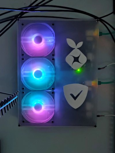
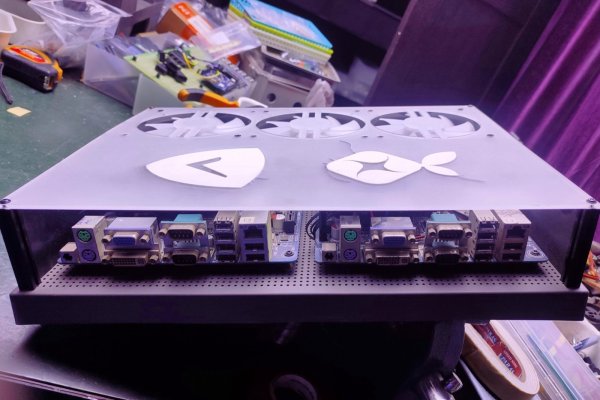
It took a while (finances are such a mess) but the first of my many mini-itx projects is done. Well, the first revision of the first one anyway (holes aren't correctly spaced in the dxf I made @tech.monk):

IMG_20230603_044807-01_PerfectlyClear.jpg

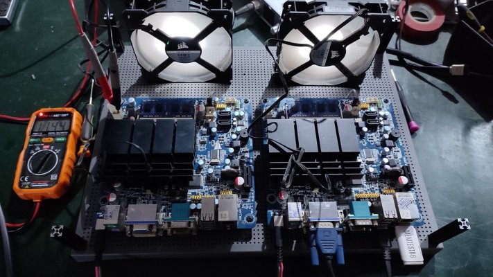
It's a dual/redundant wall-mounted adblocker server thing. It has two mini-itx motherboards each featuring that ultraslow VIA U3300 processor with 2GB of ram running Diet-Pi, one with pihole and the other with adguard. These boards are run directly off 12v and each costed Rs 900 from a dealer on OLX who salvaged them from old point-of-sale systems.

The two motherboards are mounted on a IKEA memo board, one from their SVENSAS series: https://www.ikea.com/in/en/p/svensas-pegboard-with-letters-dark-grey-40458704/

I've some rough photos that make up a mini project worklog below.

Some testing to see what the end voltage is after a 3m run, these boards will crash if the voltage falls below 11.4v:

makerbeam_svensas-03.jpg

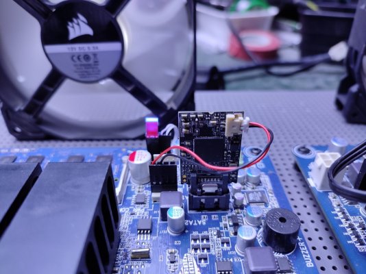
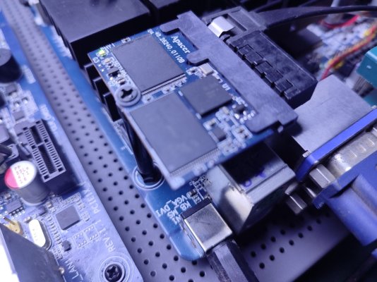
Over the years, I've collected odds and ends from buying stuff off OLX. One of these is this disk-on-module thing that plugs into the SATA port and runs off 5v, this module is 2GB:

makerbeam_svensas-04.jpg

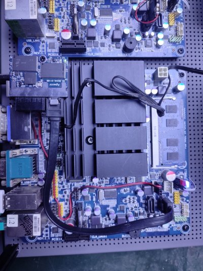
This one is from a thin client and has a standard SATA interface:

makerbeam_svensas-05.jpg

I got this short SATA cable during the Aliexpress days:

makerbeam_svensas-06.jpg

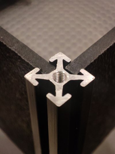
The corners have these 40mm tall pieces of 10x10 extrusion, called Makerbeam. These were purchased from tinkerforge.com and imported without customs through regular post. They help position the 3mm ABS plastic sheets I'm using as the walls of the enclosure, and they're threaded on both ends:

makerbeam_svensas-07.jpg

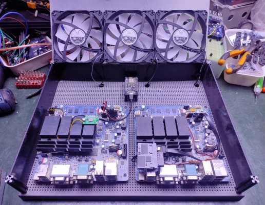
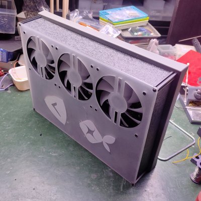
How everything is mounted, the three 120mm fans are pulled from a Silverstone FARA R1:

makerbeam_svensas-08.jpg

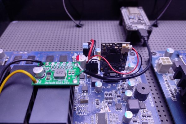
A buck converter board is used to pull down the 12v to 5v for the ESP8266 module:

makerbeam_svensas-09.jpg

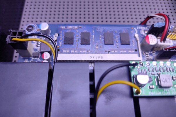
The 12v is taking from the EPS connector, which is connected to the DC jack on the rear of the motherboard:

makerbeam_svensas-10.jpg

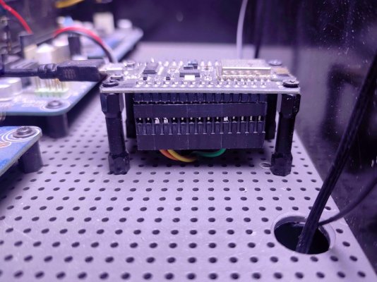
A NodeMCU clone is the wifi module I'm using to control the lighting on those fans, it's running WLED:

makerbeam_svensas-11.jpg

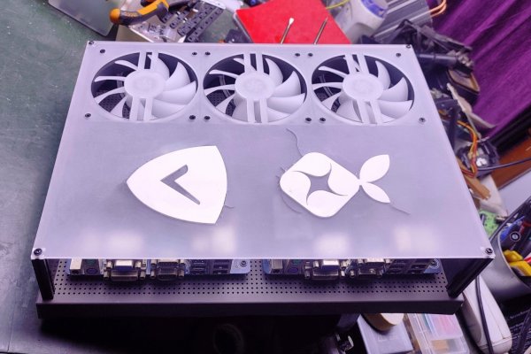
The front panel is 3mm clear acrylic that I sanded down for a frosted effect. I glued the jewel inserts before sanding, this is what ended up causing the acrylic to stress and crack:

makerbeam_svensas-12.jpg

40mm is plenty tall for the components:

makerbeam_svensas-13.jpg

I think this qualifies as my first 'scratch build' since maybe 2015?

makerbeam_svensas-14.jpg

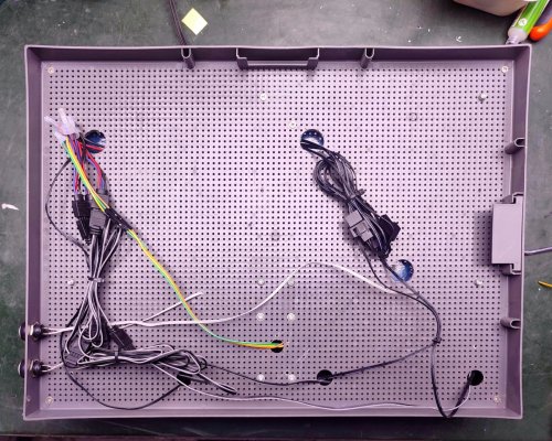
Basic cable management is at the rear (also shown are the power switches):

makerbeam_svensas-15.jpg

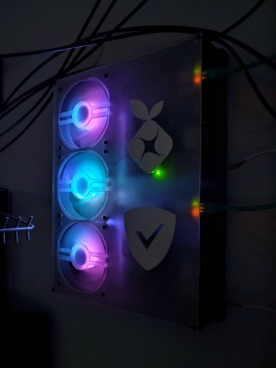
One last beauty shot:

makerbeam_svensas-02.jpg

It needs more RGB lighting, I'll fix that in the next revision since I need to redo that front panel sometime anyway.
 
Last edited:

It took a while (finances are such a mess) but the first my many mini-itx projects is done. Well, the first revision of the first one anyway (holes aren't correctly spaced in the dxf I made @tech.monk):

View attachment 169928

It's a dual/redundant wall-mounted adblocker server thing. It has two mini-itx motherboards each featuring that ultraslow VIA U3300 processor with 2GB of ram running Diet-Pi, one with pihole and the other with adguard. These boards are run directly off 12V and each costed Rs 900 from a dealer on OLX whole salvaged them from old point-of-sale systems.

The two motherboards are mounted on a IKEA memo board, one from their SVENSAS series: https://www.ikea.com/in/en/p/svensas-pegboard-with-letters-dark-grey-40458704/

I've some rough photos that make up a mini project worklog below.

Some testing to see what the end voltage is after a 3m run, these boards will crash if the voltage falls below 11.4v:

View attachment 169929

Over the years, I've collected odds and ends from buying stuff off OLX. One of these is this disk-on-module thing that plugs into the SATA port and runs off 5v, this module is 2GB:

View attachment 169931

This one is from a thin client and has a standard SATA interface:

View attachment 169932

I got this short SATA cable from the Aliexpress days:

View attachment 169933

The corners have these 40mm tall pieces of 10x10 extrusion, called Makerbeam. These were purchased from tinkerforge.com and imported without customs through regular post. They help position the 3mm ABS plastic sheets I'm using as the walls of the enclosure, and they're threaded on both ends:

View attachment 169934

How everything is mounted, the three 120mm fans are pulled from a Silverstone FARA R1:

View attachment 169935

A buck converter board is used to pull down the 12v to 5v for the ESP8266 module:

View attachment 169936

The 12v is taking from the EPS connector, which is connected to the DC jack on the rear of the motherboard:

View attachment 169937

A NodeMCU clone is the wifi module I'm using to control the lighting on those fans, it's running WLED:

View attachment 169938

The front panel is 3mm clear acrylic that I sanded down for a frosted effect. I glued the jewel inserts before sanding, this is what ended up causing the acrylic to stress and crack:

View attachment 169939

40mm is plenty tall for the components:

View attachment 169940

I think this qualifies as my first 'scratch build' since maybe 2015?

View attachment 169941

Basic cable management is at the rear (also shown are the power switches):

View attachment 169942

One last beauty shot:

View attachment 169943

It needs more RGB lighting, I'll fix that in the next revision since I need to redo that front panel sometime anyway.
Fantastic as usual. Great photographs. The build is a beautiful wall display in itself and admirers like me will hardly realize the functionality it serves if you do not tell them.
How did you setup the redundancy between the two ? Also are they connected to the network on wifi ?
 

It took a while (finances are such a mess) but the first of my many mini-itx projects is done. Well, the first revision of the first one anyway (holes aren't correctly spaced in the dxf I made @tech.monk):

View attachment 169928

It's a dual/redundant wall-mounted adblocker server thing. It has two mini-itx motherboards each featuring that ultraslow VIA U3300 processor with 2GB of ram running Diet-Pi, one with pihole and the other with adguard. These boards are run directly off 12v and each costed Rs 900 from a dealer on OLX who salvaged them from old point-of-sale systems.

The two motherboards are mounted on a IKEA memo board, one from their SVENSAS series: https://www.ikea.com/in/en/p/svensas-pegboard-with-letters-dark-grey-40458704/

I've some rough photos that make up a mini project worklog below.

Some testing to see what the end voltage is after a 3m run, these boards will crash if the voltage falls below 11.4v:

View attachment 169929

Over the years, I've collected odds and ends from buying stuff off OLX. One of these is this disk-on-module thing that plugs into the SATA port and runs off 5v, this module is 2GB:

View attachment 169931

This one is from a thin client and has a standard SATA interface:

View attachment 169932

I got this short SATA cable during the Aliexpress days:

View attachment 169933

The corners have these 40mm tall pieces of 10x10 extrusion, called Makerbeam. These were purchased from tinkerforge.com and imported without customs through regular post. They help position the 3mm ABS plastic sheets I'm using as the walls of the enclosure, and they're threaded on both ends:

View attachment 169934

How everything is mounted, the three 120mm fans are pulled from a Silverstone FARA R1:

View attachment 169935

A buck converter board is used to pull down the 12v to 5v for the ESP8266 module:

View attachment 169936

The 12v is taking from the EPS connector, which is connected to the DC jack on the rear of the motherboard:

View attachment 169937

A NodeMCU clone is the wifi module I'm using to control the lighting on those fans, it's running WLED:

View attachment 169938

The front panel is 3mm clear acrylic that I sanded down for a frosted effect. I glued the jewel inserts before sanding, this is what ended up causing the acrylic to stress and crack:

View attachment 169939

40mm is plenty tall for the components:

View attachment 169940

I think this qualifies as my first 'scratch build' since maybe 2015?

View attachment 169941

Basic cable management is at the rear (also shown are the power switches):

View attachment 169942

One last beauty shot:

View attachment 169943

It needs more RGB lighting, I'll fix that in the next revision since I need to redo that front panel sometime anyway.
Thanks @rsaeon - It is always a pleasure to watch the build logs of yours and great learning experience for us. As fellow members have noted, photos posted are visual treat.
 
Back
Top