
imran_chennai
Disciple
TLDR version. For the full write-up, please scroll below.
What did I do? : Attempted to shrink a full-sized TVS Gold keyboard to a TKL form factor.
Why did I do it? : Boredom during the lockdown. Pulled these shenanigans during Sep'2020.
How did it go? : Had no hitches modding the PCB, all the keys were functional. Poor quality paint and a horrible paint job messed up the finishing.
Key Takeaways :

-------------------------------------
Our story starts with me getting bored of tinkering with tech during the never-ending lockdown last year. I wanted a smaller keyboard to reduce the shoulder pain caused by stretching my right arm to reach the mouse. There were very few options online at that time due to the shipping restrictions. This factor combined with my necessity to re-invent and re-use got the better of me.
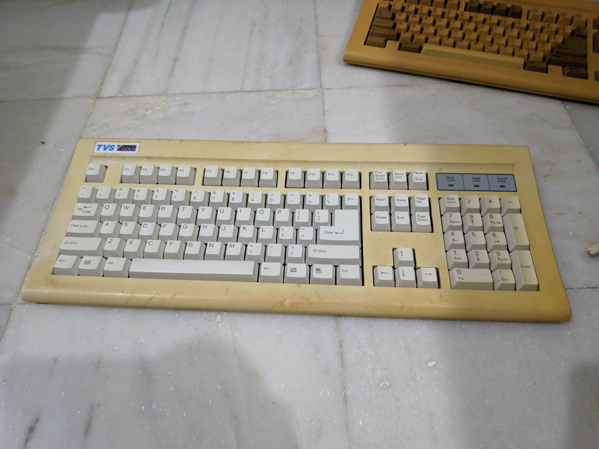
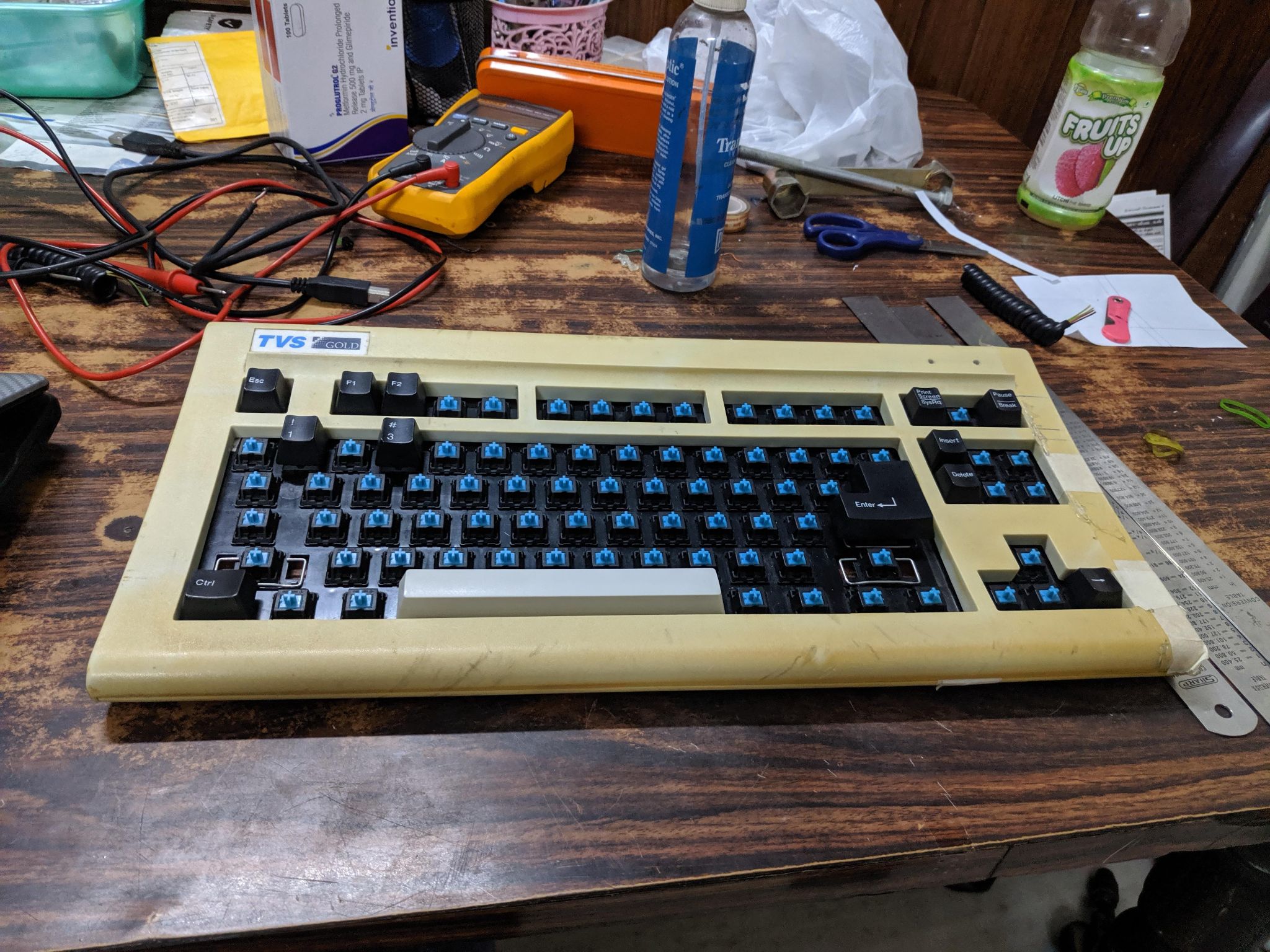
Had a white TVS keyboard (PS2) in my stash of hoarded electronics, chose it as the donor due to the faded and stained Numpad row, which eventually will be chopped off.
The donor:
Base PCB de-shrouded:
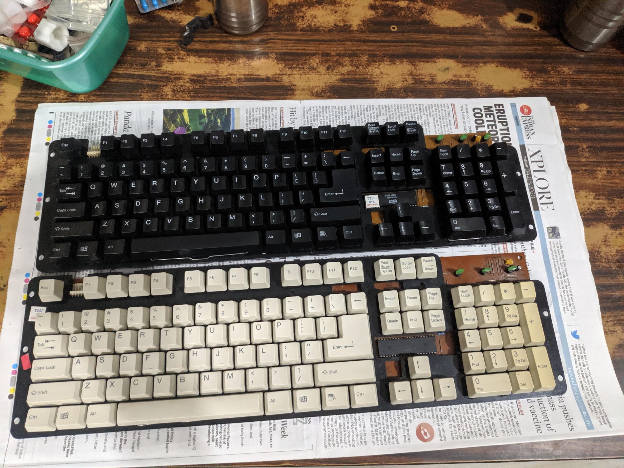
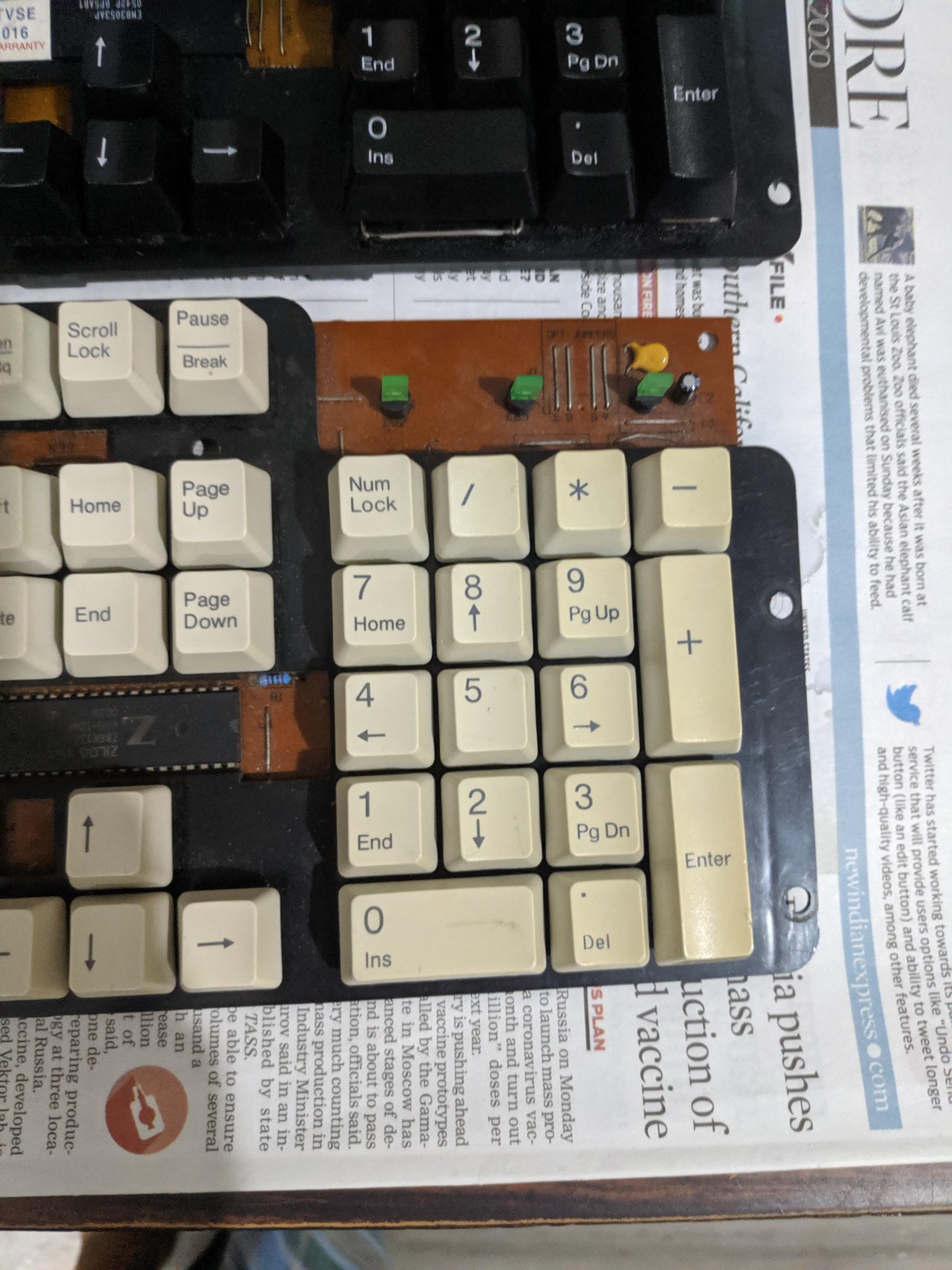
A Closer look at the aged and stained Numpad:
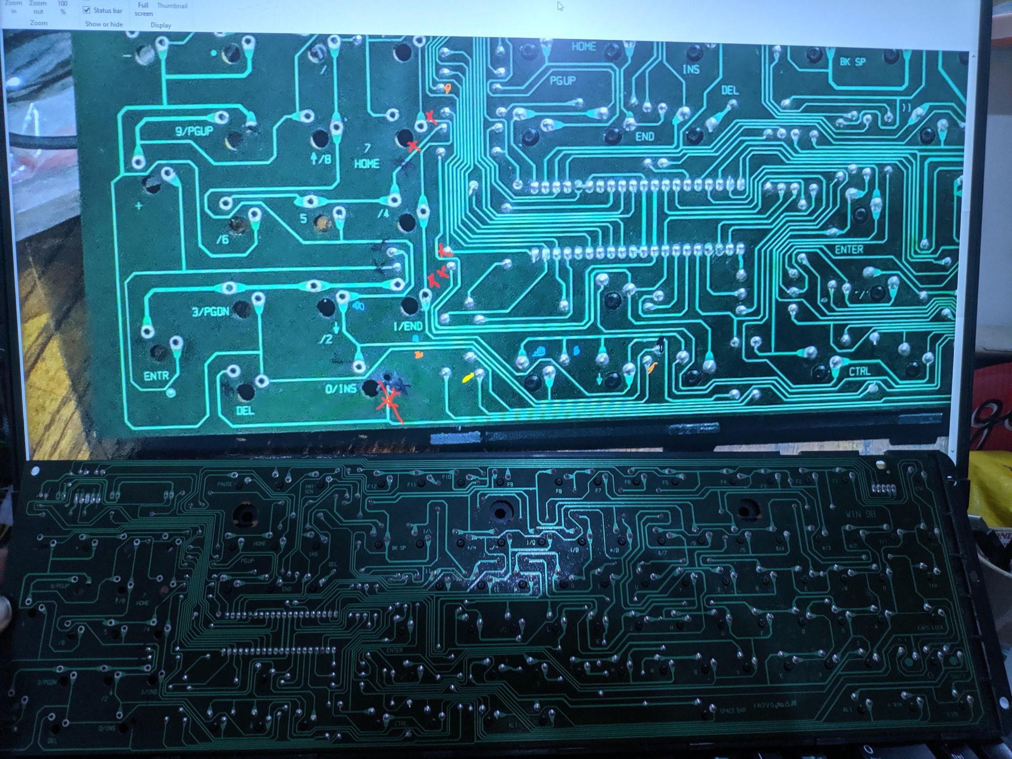
This needed to be traced 100% correctly, any error would result in some keys not working.
Using zoomed photos to understand the paths better. The first phase of tracing.
Decoding the Numpad grid and the eventual chop.
Tracing, chopping, and separating the keyboard led-status ciruit.
This will be shrunk down and re-created at a later point to be transplanted to the keyboard.
Armed with a soldering gun and knowledge of the traceroutes, I began soldering jump wires to complete the circuit.
Fair warning, I am not a pro when it comes to soldering. The layout and finish might trigger some seasoned forum members.
Hacked up and soldered TKL PCB
Adding an inline PS2 to UBS adapter for USB compatibility.
This was extracted from an off-the-shelf PS2 mouse and keyboard Y adapter.
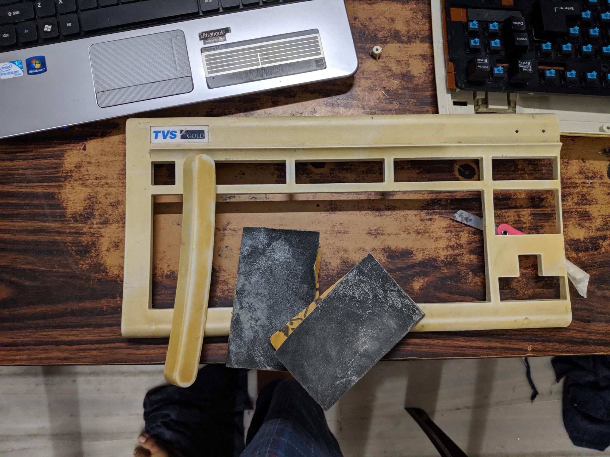
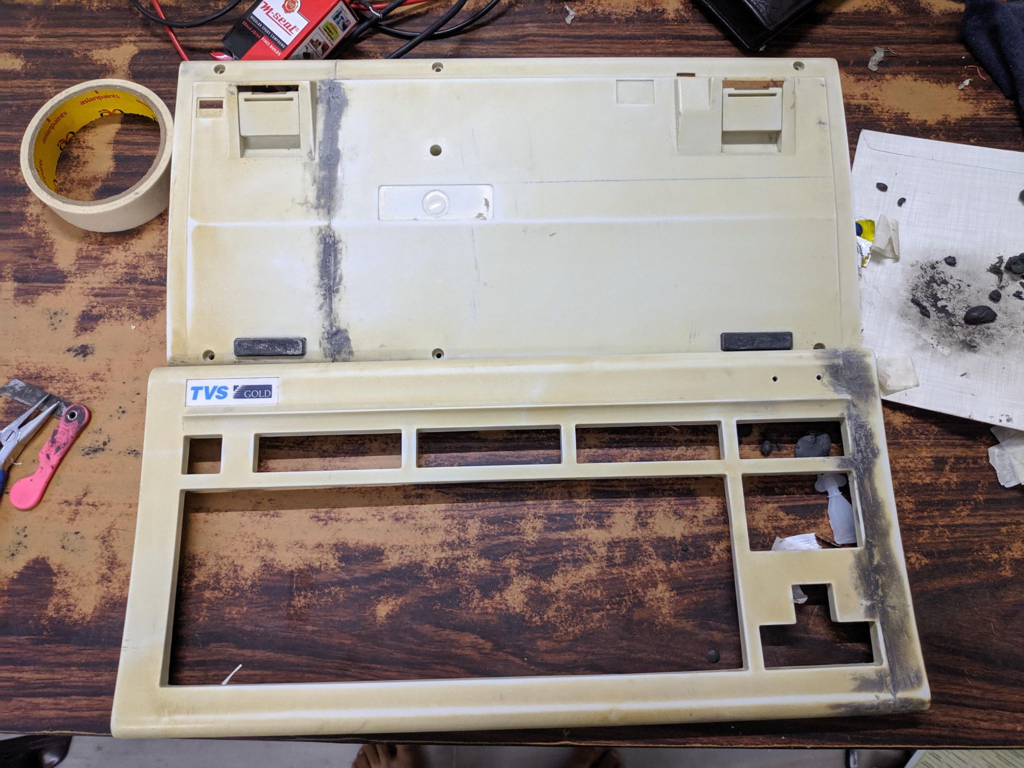
I began by laying down the PCB to measure where to cut the keyboard, in essence, I had to shrink the housing to remove the Numpad section and join it with the end caps.
This had to be done twice - once for the front fascia and again for the bottom housing.
This is how it looked after removing the TKL section, more images are below.
Use a couple of fine saw blades to keep the cut lines clean. Later sanded it down using fine-grit sandpaper to reduce the gaps between the plastic ends.
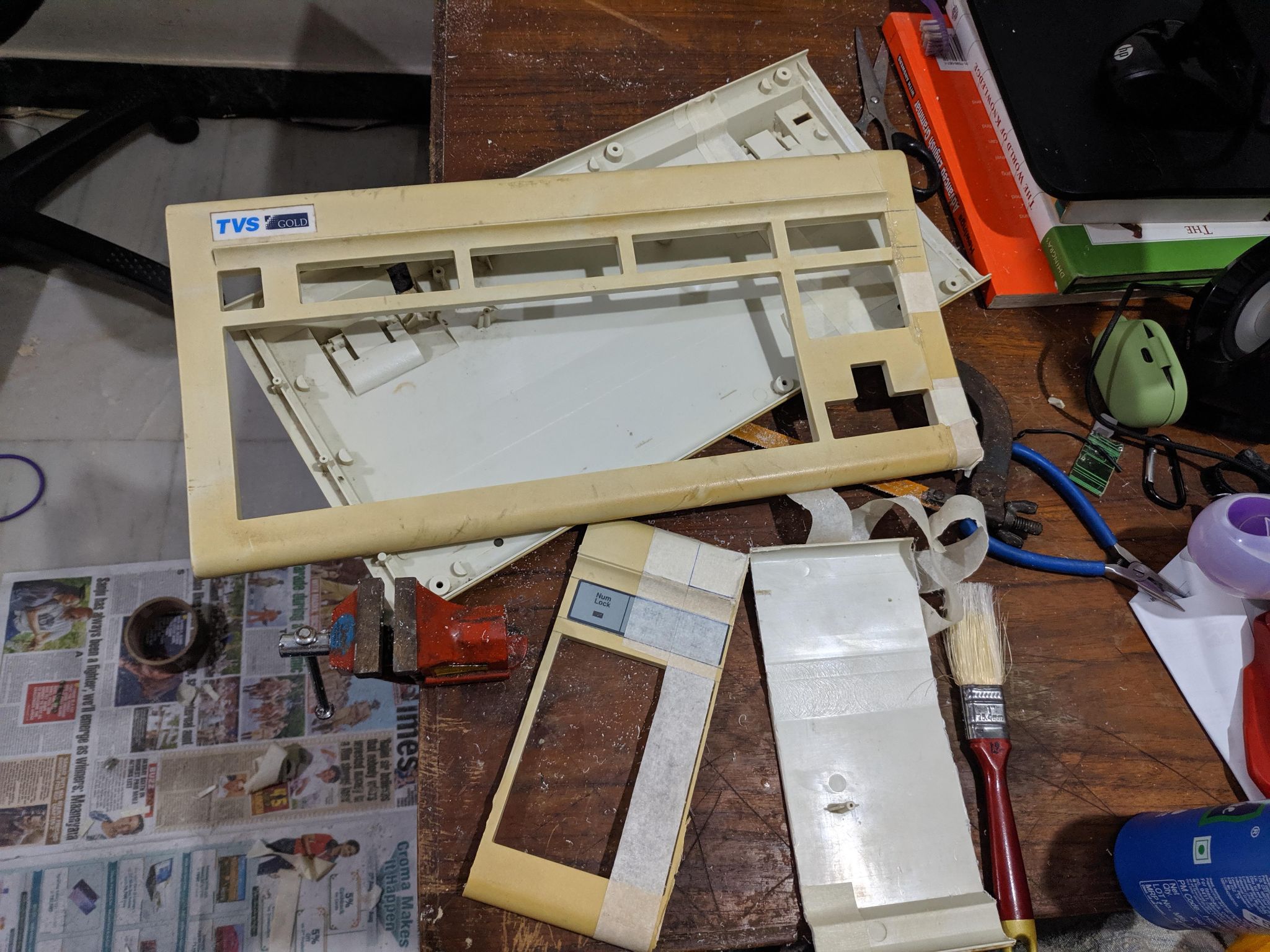
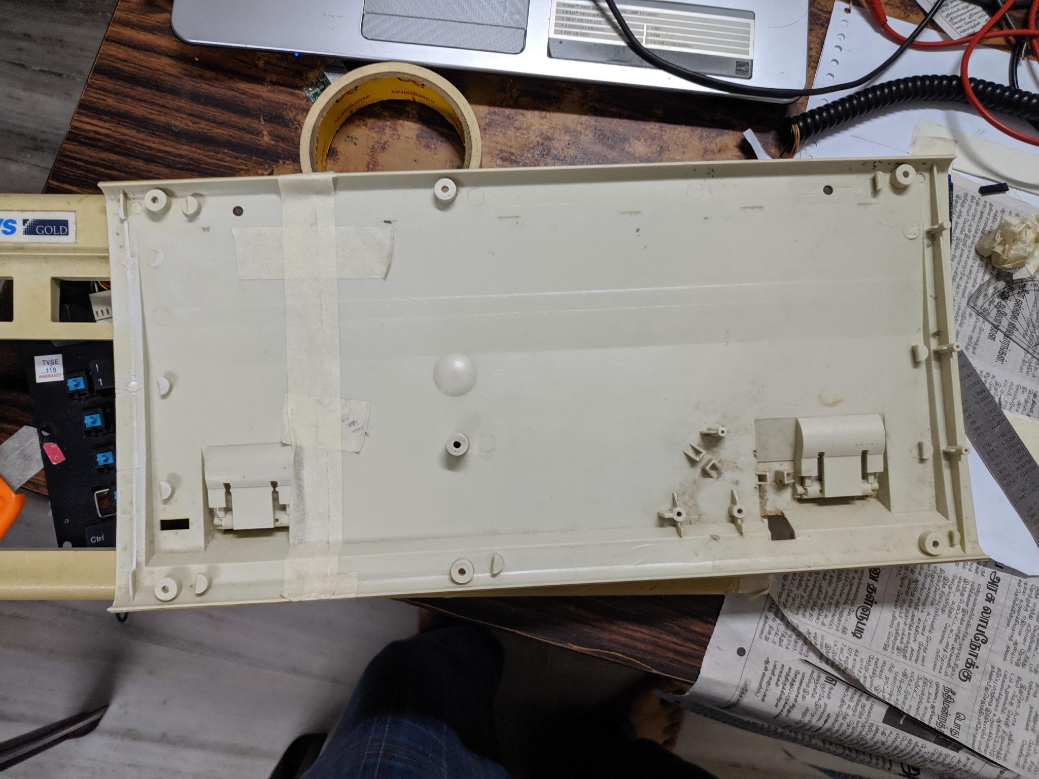
A Work in progress photos of different sections of both the bottom and top housing. Painters tape and hot glue were used to mock up the final look. Had to cut the bottom base in a slightly different manner to retain the kickstands. The house was a mess once this was done, with small particles of plastic everywhere in the room.
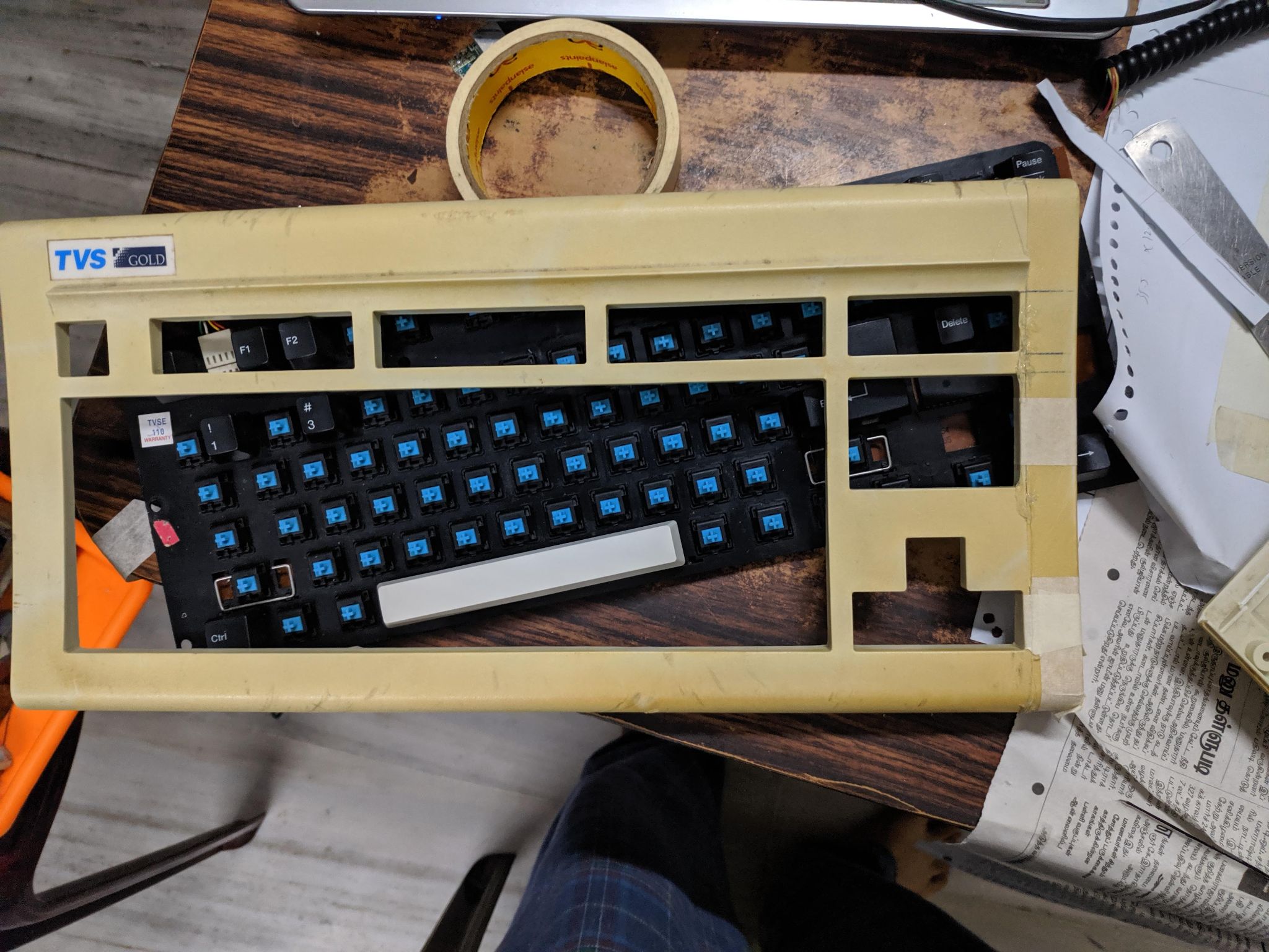
Partial test fit to check clearances. Everything checks out.
Used a cheapo method of using MSeal epoxy to close the gaps. Used fine-grit sandpaper to smooth out and remove any excess material.
Both sides of the housing shrunk, cleaned, and ready for paint.
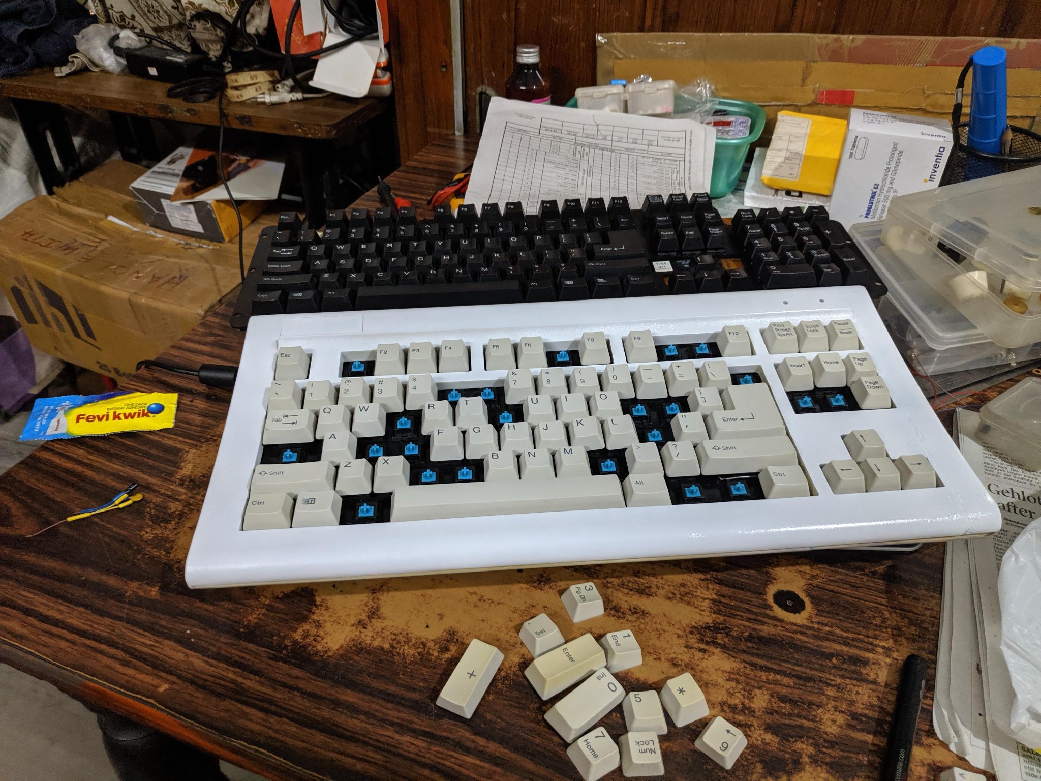
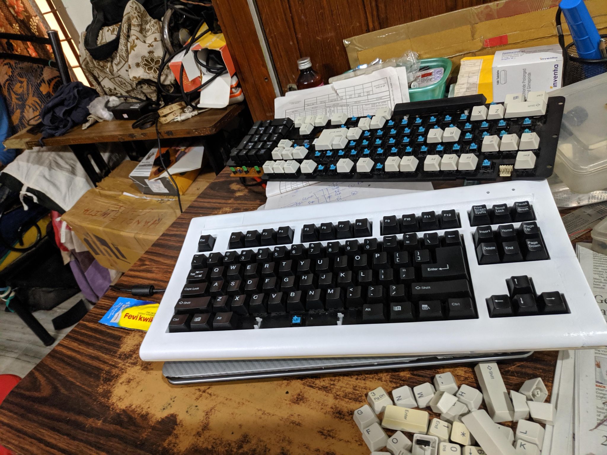
After a few coats of white spray paint and letting it dry for two days, it started to look pretty good.
Tried out the original white keycaps initially. Did not like the look, swapped them out for black keycaps for a contrasting black on white look.
W
Lockdown lifted and I instantly bought a Cosmic Byte TKL keyboard to replace the abomination that I had created. In hindsight, I should have used the keyboard as-is without paint and call it “patina” or at least had the patience to prep for a quality paint job.
This silly creation of mine is currently tucked away among other things waiting for its next stage of revival.
Thanks for reading through this post!
What did I do? : Attempted to shrink a full-sized TVS Gold keyboard to a TKL form factor.
Why did I do it? : Boredom during the lockdown. Pulled these shenanigans during Sep'2020.
How did it go? : Had no hitches modding the PCB, all the keys were functional. Poor quality paint and a horrible paint job messed up the finishing.
Key Takeaways :
- TVS Gold is a good starting point for learning about keyboard modding. These are cheap, readily available, and are surprisingly robust.
- Never use cheap rattle can paint on plastic, it spoils the end product
- There is a reason why mass production exists
- My family hates clicky blue switches
-------------------------------------
Our story starts with me getting bored of tinkering with tech during the never-ending lockdown last year. I wanted a smaller keyboard to reduce the shoulder pain caused by stretching my right arm to reach the mouse. There were very few options online at that time due to the shipping restrictions. This factor combined with my necessity to re-invent and re-use got the better of me.
Had a white TVS keyboard (PS2) in my stash of hoarded electronics, chose it as the donor due to the faded and stained Numpad row, which eventually will be chopped off.
The donor:
Base PCB de-shrouded:
A Closer look at the aged and stained Numpad:
Phase 1 - PCB Mod:
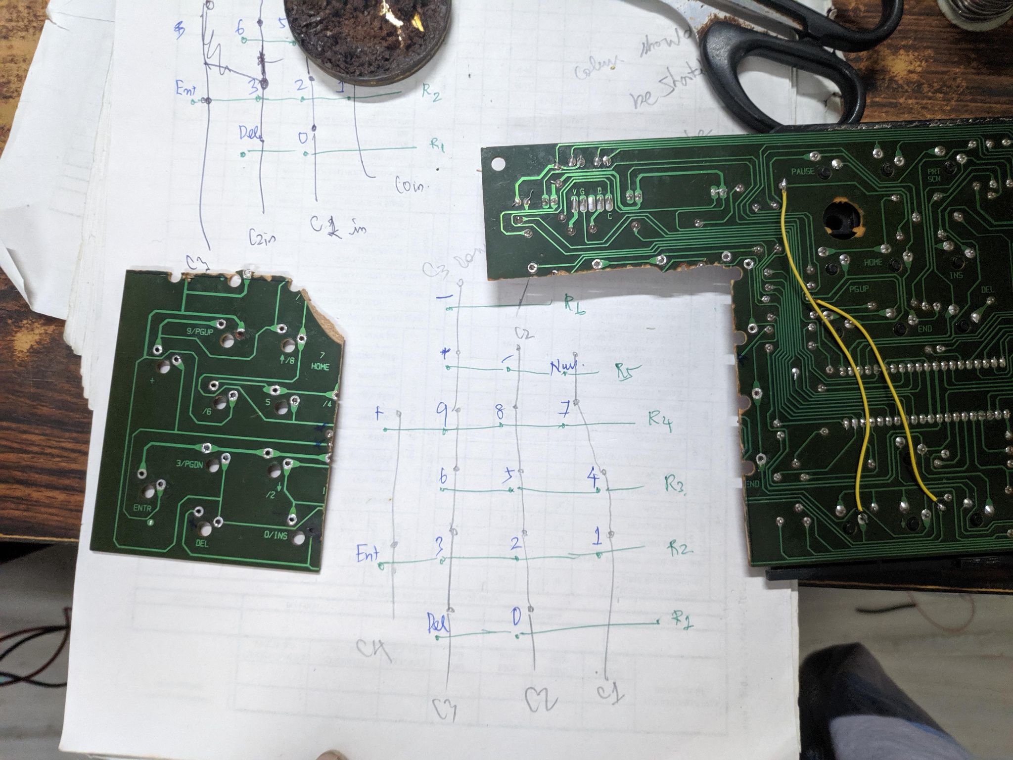
Began the arduous process of tracing the contacts to recreate the circuit diagram for the Numpad side of the PCB.This needed to be traced 100% correctly, any error would result in some keys not working.
Using zoomed photos to understand the paths better. The first phase of tracing.
Decoding the Numpad grid and the eventual chop.
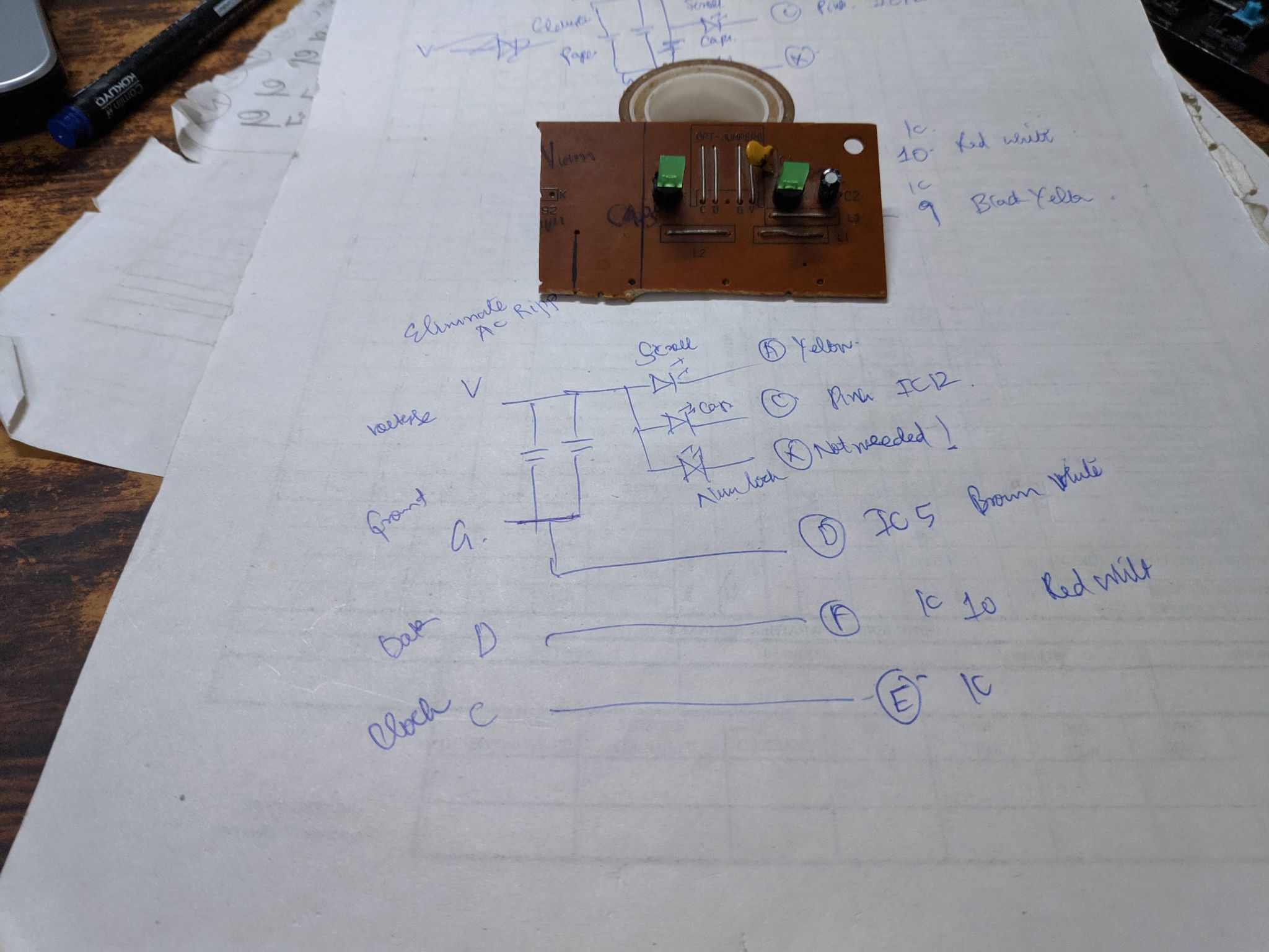
Tracing, chopping, and separating the keyboard led-status ciruit.
This will be shrunk down and re-created at a later point to be transplanted to the keyboard.
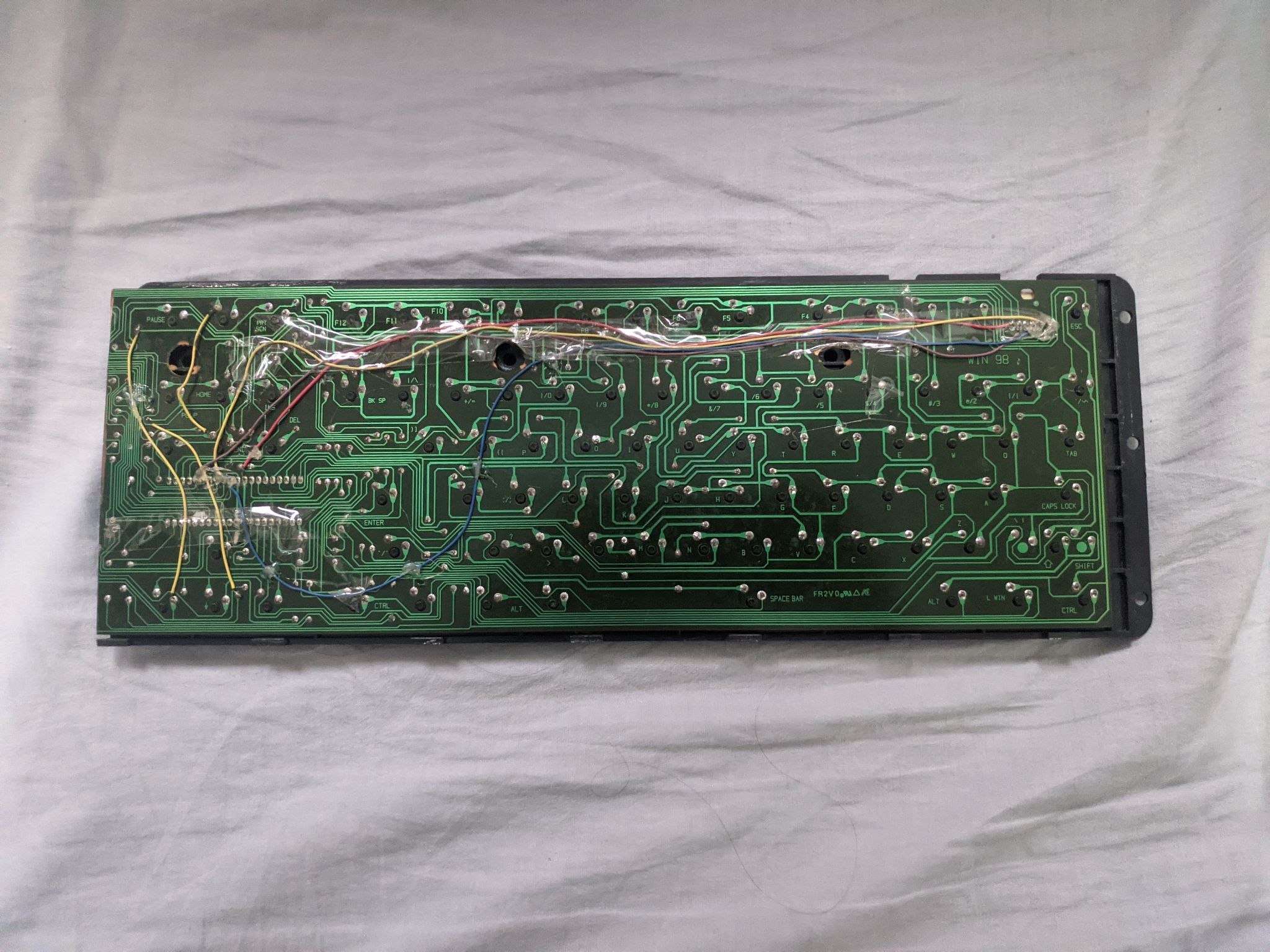
Armed with a soldering gun and knowledge of the traceroutes, I began soldering jump wires to complete the circuit.
Fair warning, I am not a pro when it comes to soldering. The layout and finish might trigger some seasoned forum members.
Hacked up and soldered TKL PCB
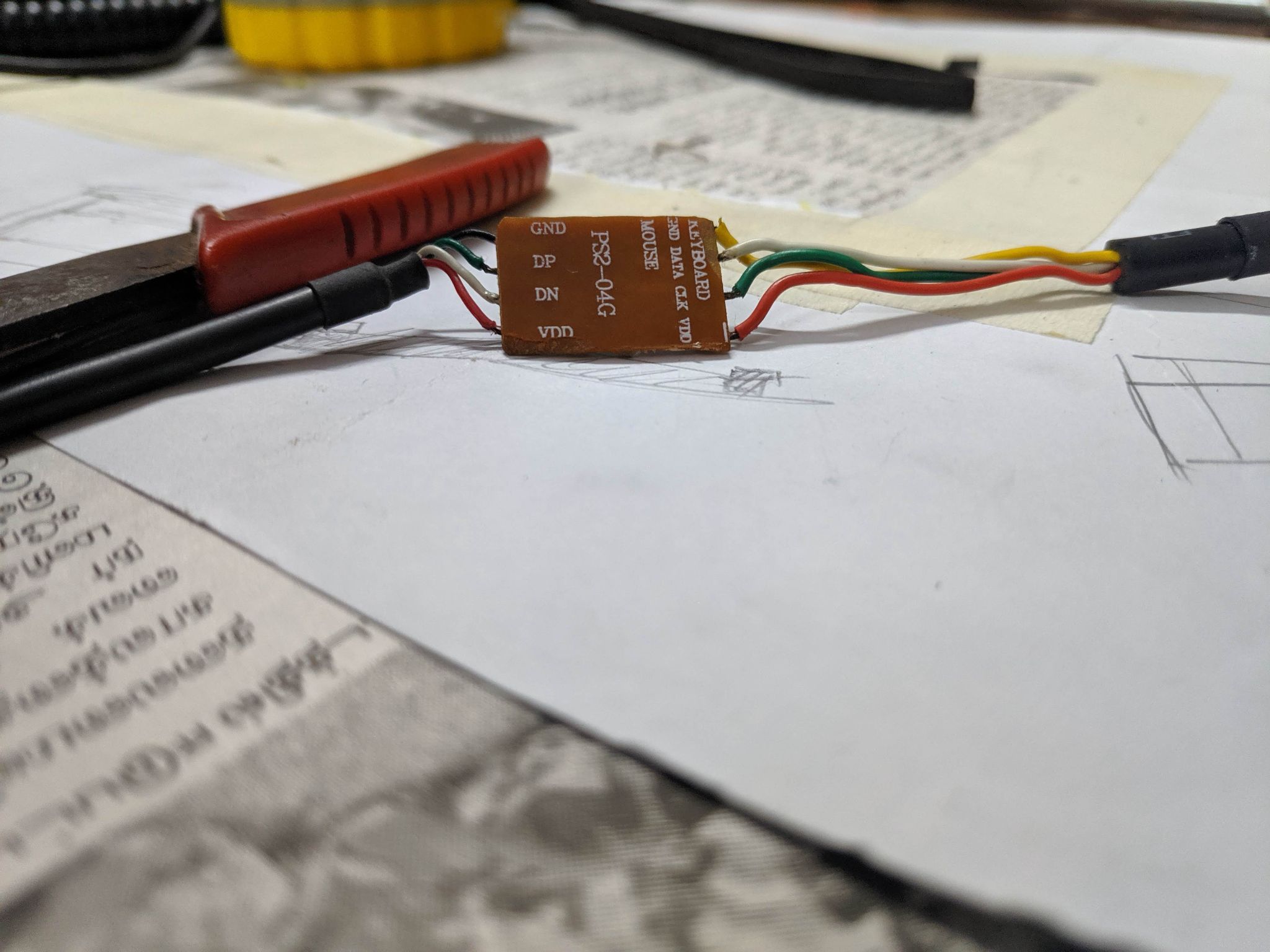
Adding an inline PS2 to UBS adapter for USB compatibility.
This was extracted from an off-the-shelf PS2 mouse and keyboard Y adapter.
Phase 2 - Enclosure Mod
This was easily the most demanding part of the overall process as there are options for no do-overs. Measure twice, cut once.I began by laying down the PCB to measure where to cut the keyboard, in essence, I had to shrink the housing to remove the Numpad section and join it with the end caps.
This had to be done twice - once for the front fascia and again for the bottom housing.
This is how it looked after removing the TKL section, more images are below.
Use a couple of fine saw blades to keep the cut lines clean. Later sanded it down using fine-grit sandpaper to reduce the gaps between the plastic ends.
A Work in progress photos of different sections of both the bottom and top housing. Painters tape and hot glue were used to mock up the final look. Had to cut the bottom base in a slightly different manner to retain the kickstands. The house was a mess once this was done, with small particles of plastic everywhere in the room.
Partial test fit to check clearances. Everything checks out.
Phase 3 - Finishing Touches
Satisfied with the looks and tolerances, I started to glue the plastic cuts together using feviquick and a couple of support pieces.Used a cheapo method of using MSeal epoxy to close the gaps. Used fine-grit sandpaper to smooth out and remove any excess material.
Both sides of the housing shrunk, cleaned, and ready for paint.
After a few coats of white spray paint and letting it dry for two days, it started to look pretty good.
Tried out the original white keycaps initially. Did not like the look, swapped them out for black keycaps for a contrasting black on white look.
W
Phase 4 - Regret and Learning
I had used the keyboard in this condition for a couple of weeks, no issues with the operation. But, the finishing started to show issues. Due to the cheap nature of the spray paint, it did not play well with the plastic housing and began to stick to objects that were resting on the keyboard, resulting in paint peel.Lockdown lifted and I instantly bought a Cosmic Byte TKL keyboard to replace the abomination that I had created. In hindsight, I should have used the keyboard as-is without paint and call it “patina” or at least had the patience to prep for a quality paint job.
This silly creation of mine is currently tucked away among other things waiting for its next stage of revival.
Thanks for reading through this post!
Last edited: