CPU/Mobo Using Windows Tablet without battery and screen, like SBC or CPU... Help

Skyh3ck

Adept
Hello I had this Unbranded UB15MS10 Windows tablet for long time, purchased from one member here., it worked for few months and later screen broke.

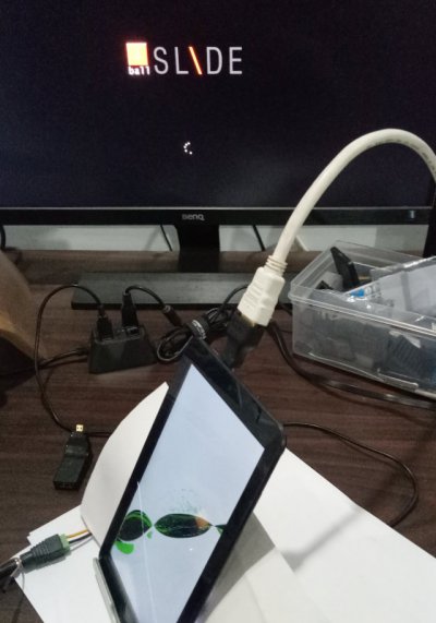
The good thing is only the screen is gone, but when i connect the Tablet with HDMI monitor or TV, it is working fine.

Now i want to use this tablet or its motherboard just like SBC or standalone CPU. Specification of the tablet is as follows


Intel Atom Z 3000 category processor, 2 GB RAM, 32 Storage, Wifi and Bluetooth, 1 Micro HDMI, 1 Micro USB to charge and connect device

It has everything inbuilt to run as a low end or media center or experiement pc..

now, my problem is that i can not use the Charger and usb OTG at the same time, so if i want to use it as a cpu, it should get power from somwehre else other than micro usb.
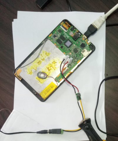
i am thinking to remove the battery and make something that can power the device from battery connnector on motherboard and use the micro usb to connect usb hub.

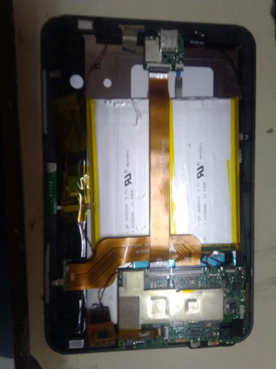
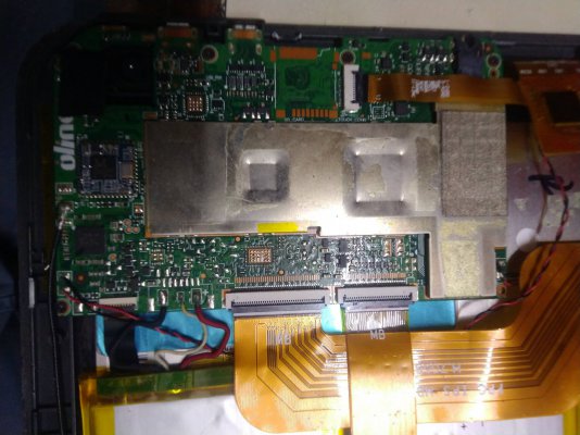
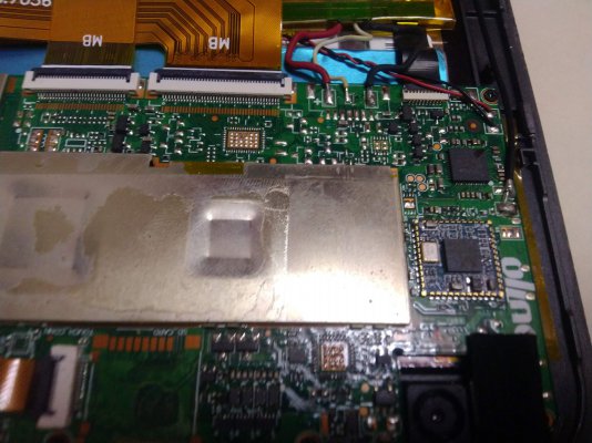
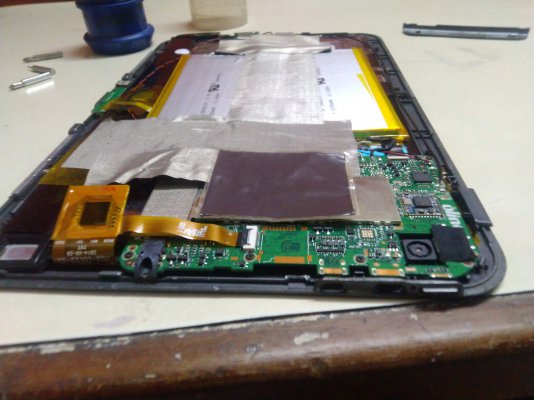
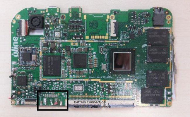
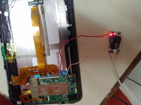
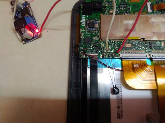
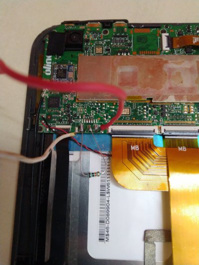
here is the pic of motherboard. the battery has 3 cable, Red, Black and White. and the battery states it has 3.7 volt charge, i have never done this before just wanted to know guidance and help here. it s DIY project to make a useful pc out of broken tablet.

please check the images, if my problem is solved, then i will get a box prepared for this.

1. can i just cut open any micro usb cable and connect the cable on the battery connector on motherboard, do i need kind of cirtuit or battery regulator in between
2. is there any way i can expand the current single micro usb to few more by addition or soldering any more card or expansion

please suggest
 

Attachments

  • IMG_20210905_185831.jpg
    IMG_20210905_185831.jpg
    180.2 KB · Views: 163
  • IMG_20210905_190149.jpg
    IMG_20210905_190149.jpg
    282.7 KB · Views: 174
  • IMG_20210905_191012.jpg
    IMG_20210905_191012.jpg
    298 KB · Views: 164
  • IMG_20210905_191309.jpg
    IMG_20210905_191309.jpg
    232.6 KB · Views: 136
  • US15MS10.JPG
    US15MS10.JPG
    119.3 KB · Views: 170
I'm working on something similar with an iBall Slide i701, it's a Z3735 based tablet with the same limitations as yours. I did try with a powered OTG hub, but this method only works with certain revisions of these tablets, and it has not worked for me.

I'm experimenting with powering it with a mini DC-DC buck converter through the battery connection:


I have set to output 4.2v and the tablet does boot into the bios and windows start up repair.

The eMMC appears to be corrupted so most likely I'll have to have it boot off a USB storage device, so this project has been put on hold for a while.
 

Attachments

  • 701b.jpg
    701b.jpg
    117.2 KB · Views: 207
  • 701a.jpg
    701a.jpg
    89.2 KB · Views: 182
Thanks i am not alone... It's so frustrating ti know that this devices being smart and advanced.. but after breaking if one single thing they just stop working or become useless...

Companies ate designing things so weirdly
Strangely my tablet also always goes in repair mode when I soft restart it.. strange but it's not due to emmc storage fault.. it's something to battery and charging
 
I'm working on something similar with an iBall Slide i701, it's a Z3735 based tablet with the same limitations as yours. I did try with a powered OTG hub, but this method only works with certain revisions of these tablets, and it has not worked for me.

I'm experimenting with powering it with a mini DC-DC buck converter through the battery connection:


I have set to output 4.2v and the tablet does boot into the bios and windows start up repair.

The eMMC appears to be corrupted so most likely I'll have to have it boot off a USB storage device, so this project has been put on hold for a while.

Did you removed battery completely.. and how is that converter working.. also is there any custom 3D printed chassis option..

Also how you can extend the usb ports
 
Did you removed battery completely.. and how is that converter working.. also is there any custom 3D printed chassis option..

Yes I removed the battery completely, in my case the battery started expanding which led to the eventual cracking of the screen since I left it plugged in all the time with fliqlo as a clock:

170527-193508.jpg


I did purchase a replacement battery, but I couldn't get it it charge properly because the third wire is a thermistor that isn't the standard 10k ohms for most three wire batteries.

The little dc-dc converter board converts a higher voltage to a lower preset voltage. I'm using a 12V/1A power adapter and I used a basic multimer to adjust the trimmer to 4.2v.

As for chassis, I haven't decided yet, but I do like the enclosures sold by probots.co.in for these kind of projects. 3D printing is cool, but a ready made enclosure or even laser cut acrylic from a sign maker shop is far more accessible.

Also how you can extend the usb ports

I'm using an old powered usb hub

Won't something like this work? It works for a Firestick and allows connecting external 2.5" USB powered HDD when using a 5V 2A power adapter. The USB A female port can also be extended via a hub.

The seller responds in the questions section that it won't work for Android tablets, just the firestick. I really wanted to try it out, but I have a couple of those and it's a hit or a miss if it works with a tablet.
 
well, what if i do not remove the battery and just add the TP4056 module additionally directly to the red and black

so that other usb is free?

Will that work

also TP4056 is 1A max, can i connect 2A charger to it, will that work or harm the system ?

 
Yes, that should work just fine.

When it comes to power being provided by any source, voltage is insisted upon and amperage is allowed. So a 5V 2A power supply will insist on giving 5v (not negotiable) but the circuit/load is allowed to take any amount of amps between 0 and 2A. Over 2A, the voltage may drop or the power supply may cut off.

Having a 2A power supply for a 1A charger circuit works just as fine as a 1A power supply or 10A power supply as the charging module circuit will consume only what it needs.

For safety reasons, don't use something like a 10A power supply. This is because if something should go wrong, like a fault in the circuit, or a short somewhere, then the load (the TAP4056) can draw upto 10A from the power supply, which may be enough to cause a fire hazard if there are flammable materials present. A 2A fuse would be a good idea if you're using a high amperage power source (over 5A).
 
No I will only use mobile phone charger likr 5v 1 amp or 5v 2amp

Now how can I connect the circuit.. what are the B+ B - and what are out+and out -

Whatit has two separate connection..

Where can I connect the cable from battery to tp4056
 
Connect the battery to the B points, and connect the tablet to the OUT points.

The datasheet for this module states that your load should not be connected when charging, so this setup may not work as you intend since you would need to turn off the tablet in order to charge the battery.
 
Connect the battery to the B points, and connect the tablet to the OUT points.

The datasheet for this module states that your load should not be connected when charging, so this setup may not work as you intend since you would need to turn off the tablet in order to charge the battery.

So this is a big hurdle...

I want to keep the power connected to the motherboard just like any normal desktop computer...

Is there any way

1 ). I keep the battery connected and also connect to power.. so it dan charge and provide power at same time...

2) I remove the battery and and provide direct to motherboard.. from where battery was connected..

Any idea how can I achiev one of this
i have purchased both TP4056 and LM2596 and i was about to use TP4056.

But then i came to know that TP4056 can not be used to charge and load at the same time, so it wont serve the purpose

I will go with LM2596

Is there any other module that can be used, instead of 4056, some thing that can charge and load at the same time with safety feature...
 
Last edited:
You could try using that TPA4056 module without connecting the battery, it should be able to power the tablet.

yes, but i have seen videos that if motherboard cant detect the battery,, after some use it will switch off thinking that battery is draining

i have seen few videos where people used some capasitor, what is the use of capasitor here, and which one i use
 
Ok so I removed the battery and connected the LM2596 module buck converter to the motherboard..

I get 3.7v to the module and motherboard.. but tablet is not starting up.. the red LED is blinking in tab.. which means Tablet is indicating a low battery level...

Is there any way I can fool tablet to think battery is connected..
 

Attachments

  • IMG_20210929_155807.jpg
    IMG_20210929_155807.jpg
    195.6 KB · Views: 217
It's possible the tablet is using the third wire as a sense wire to check if the battery is connected. You could try using a 10K resister betweeen the third wire and ground (the negative connection).
 
Ok so I tried 10k transistor, 10k thermistor.. but it did not switch on the tablet...

Then at last i removed the internal circuit from battery..

Which look likes a long thin circuit..

Any idea now what is this and how it works
 

Attachments

  • IMG_20210930_152450.jpg
    IMG_20210930_152450.jpg
    262.1 KB · Views: 148
  • IMG_20210930_151637.jpg
    IMG_20210930_151637.jpg
    283.5 KB · Views: 147
So it's likely that the tablet thinks that the 3.7v from the charging module is too low, and so it's preventing a power on in an attempt protect the battery from further discharge. You can confirm this by also connecting the USB charger and then trying to turn on the tablet.

If you have a multimeter, you could check the resistance between the middle wire and ground in order to have a confirmation of the internal thermistor of the battery. I haven't got my battery, I had to dispose of it when it started to expand and emit gasses.

It might just be easier to go with a dc-dc converter like what I used, my tablet turns on with it set to output 4.1v.
 
Back
Top