X299 AORUS Gaming 7 Review
The Intel’s X299 platform had little effect on the high end PC market. Consumers and we all were excited about the new platform, but after the VRM heating issue of X299 motherboards and announcement of the new AMD’s show-stopping 16-core Threadripper CPUs now consumers have a lot to choose from.
Anyway today we are reviewing another X299 motherboard, this time is a Gigabyte product the AORUS X299 Gaming 7 motherboard with RGB Fusion, Digital LED, Triple M.2 with Thermal Guard, ESS SABRE 9018 DAC, Killer DoubleShot™ Pro, Front & rear USB 3.1 Gen 2 Type-C and more.
Now let’s see what this AORUS board have for us.
Features
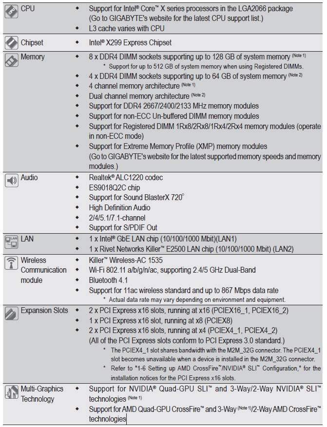
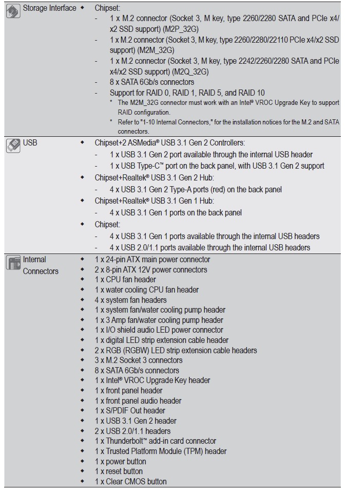
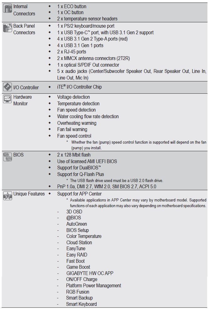
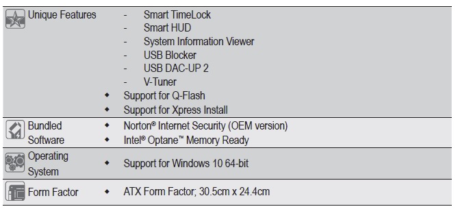
Specifications
Package
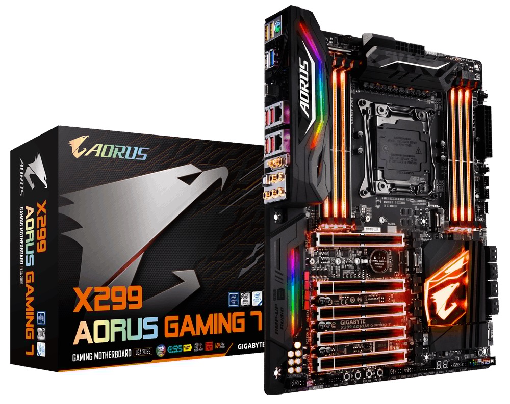
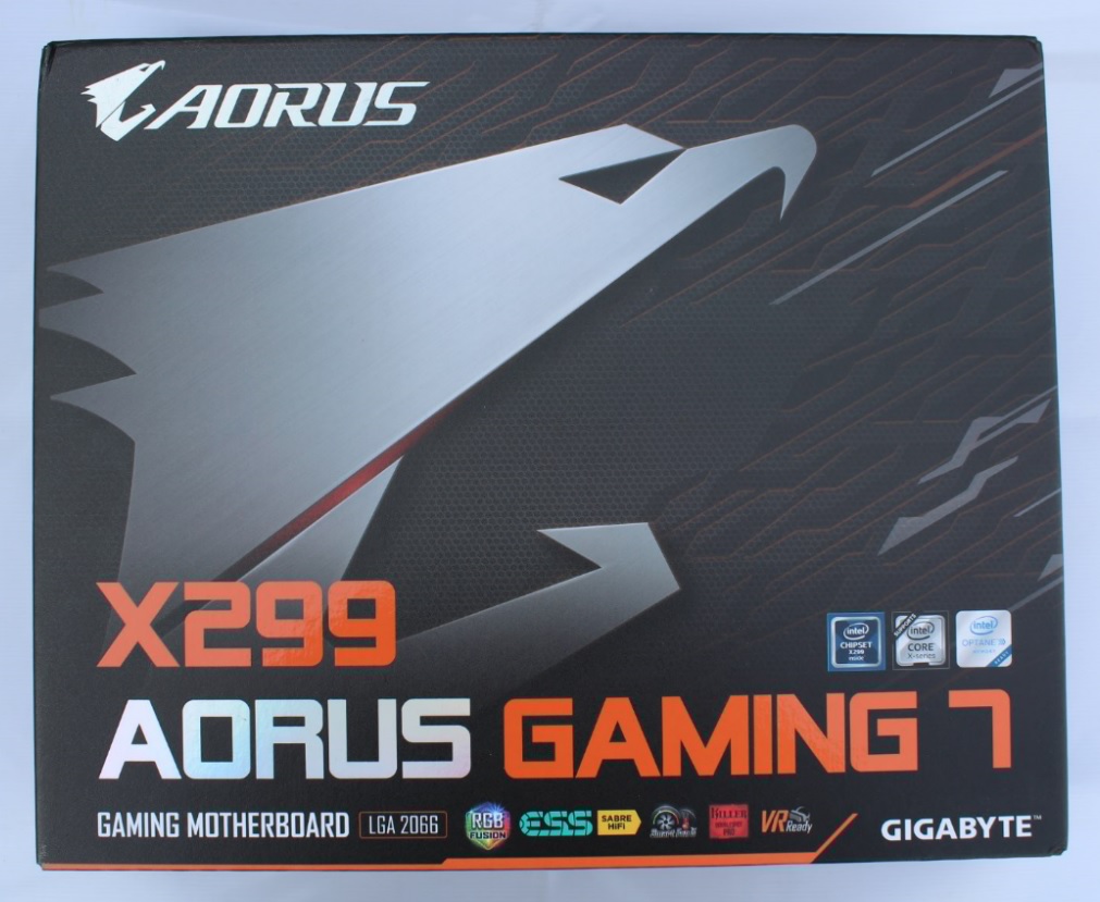
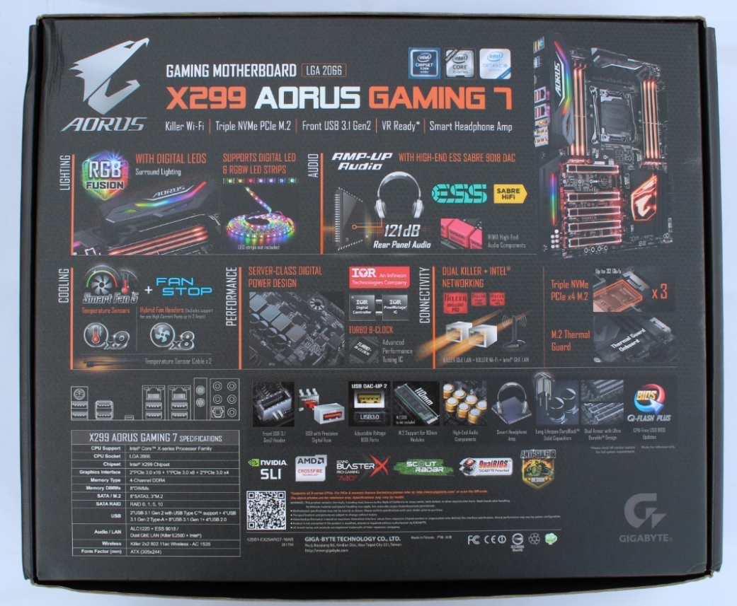
Motherboard comes in a mate gray/orange colour finishing box with a big AORUS logo with motherboard model no. in front At the rear of the box, we find that Gigabyte goes into great detail on the specifications of the motherboard
Inside the box
Looks
Board is a solid build in the mate black colour theme.
Layout
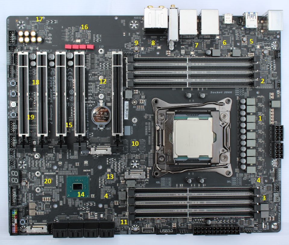
Detailed layout of board.
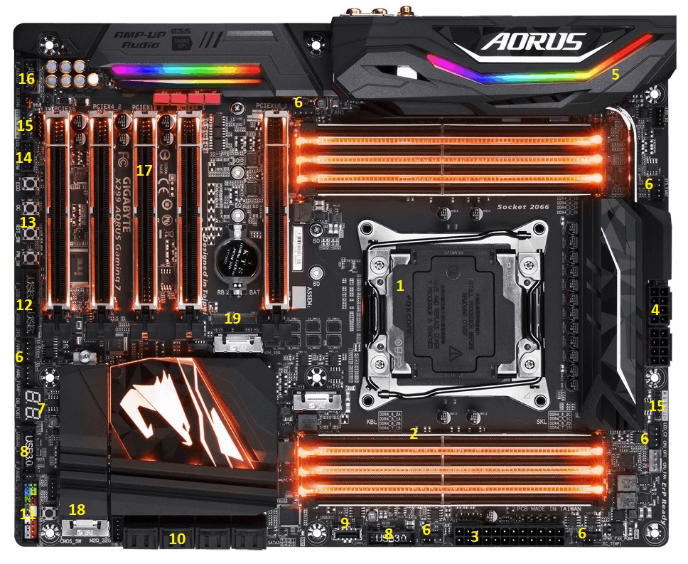
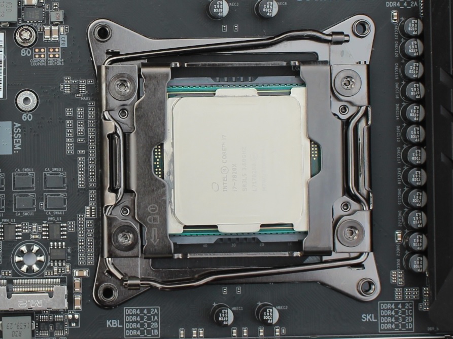
1. New Intel LGA 2066 Socket Supports New Intel Core X-series Processor Family
2. 8 x DDR4 memory slots, support up to 128GB. Quad channel memory architecture
Overclock DDR4 memory frequencies up to 4400MHz.
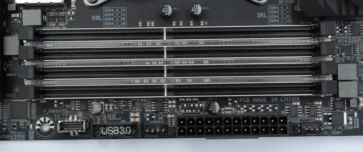
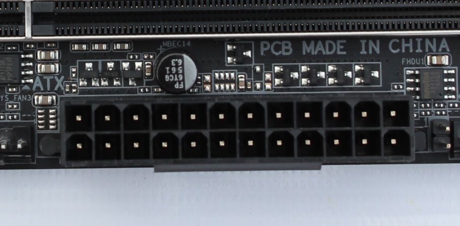
3. ATX Power connector (24-pin EATXPWR)
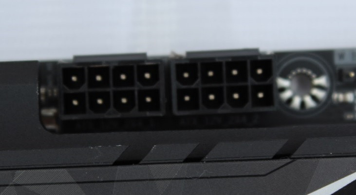
4. 2 x ATX CPU Power Connector (8-pin + 8 Pin ATX12V).
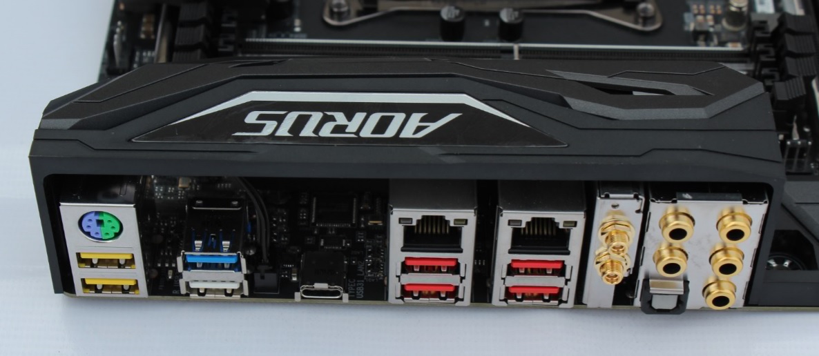
5. Back I/O ports : PS/2 keyboard/mouse port, USB Type-C™ port, with USB 3.1 Gen 2 support, 4 x USB 3.1 Gen 2 Type-A ports (red), 4 x USB 3.1 Gen 1 ports, 2 x RJ-45 ports, 2 x MMCX antenna connectors (2T2R), optical S/PDIF Out connector, 5 x audio jacks (Center/Subwoofer Speaker Out, Rear Speaker Out, Line In, Line Out, Mic In))
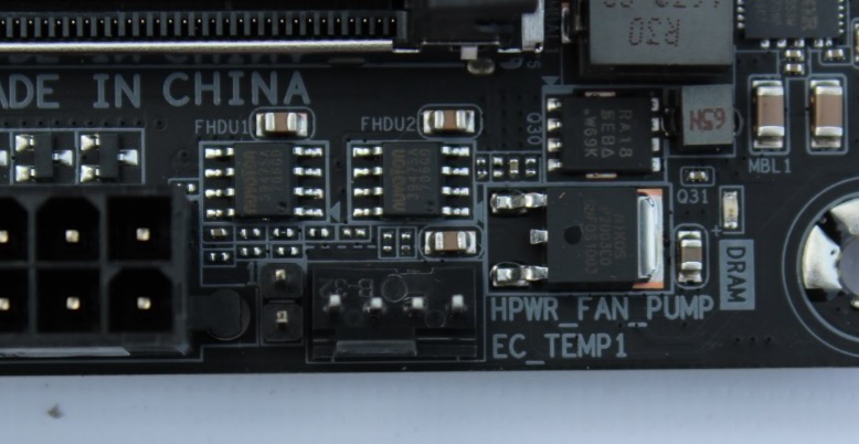
6. Fan Connectors : 1 x CPU fan header, 1 x water cooling CPU fan header, 4 x system fan headers, 1 x system fan/water cooling pump header, 1 x 3 Amp fan/water cooling pump header
7. Debug Code display.
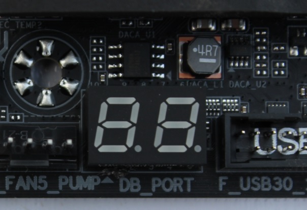
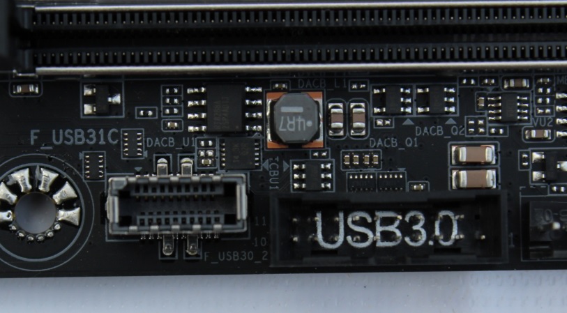
8. 9.Front 2 X USB 3.1 Gen1 connectors and USB 3.1 Gen2 Type-C port.
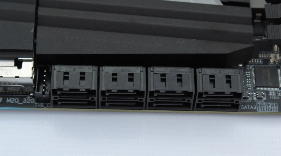
10.8 x SATA 6Gb/s connectors.
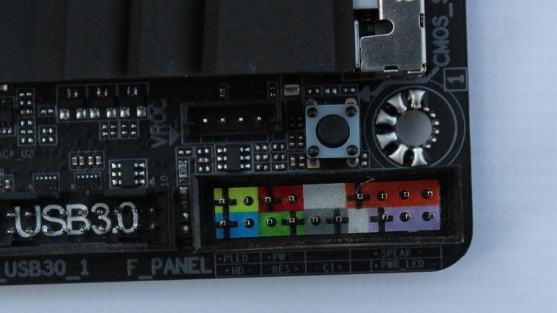
11. Front Panel Connector
12. 2 x USB 2.0 Connectors
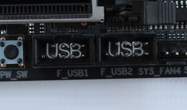
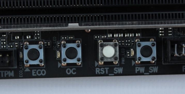
13. Power button, reset button, ECO button and OC button
14. Trusted Platform Module (TPM) header (2x6 pin, for the GC-TPM2.0_S module only)
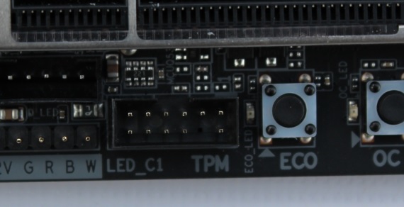
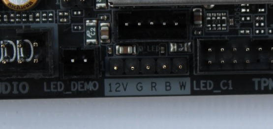
15. 2 x RGB (RGBW) LED strip extension cable headers
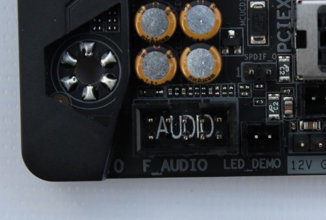
16. Front panel audio connector
17. Expansion Slots : 2 x PCI Express x16 slots, running at x16 (PCIEX16_1, PCIEX16_2), 1 x PCI Express x16 slot, running at x8 (PCIEX8), 2 x PCI Express x16 slots, running at x4 (PCIEX4_1, PCIEX4_2)
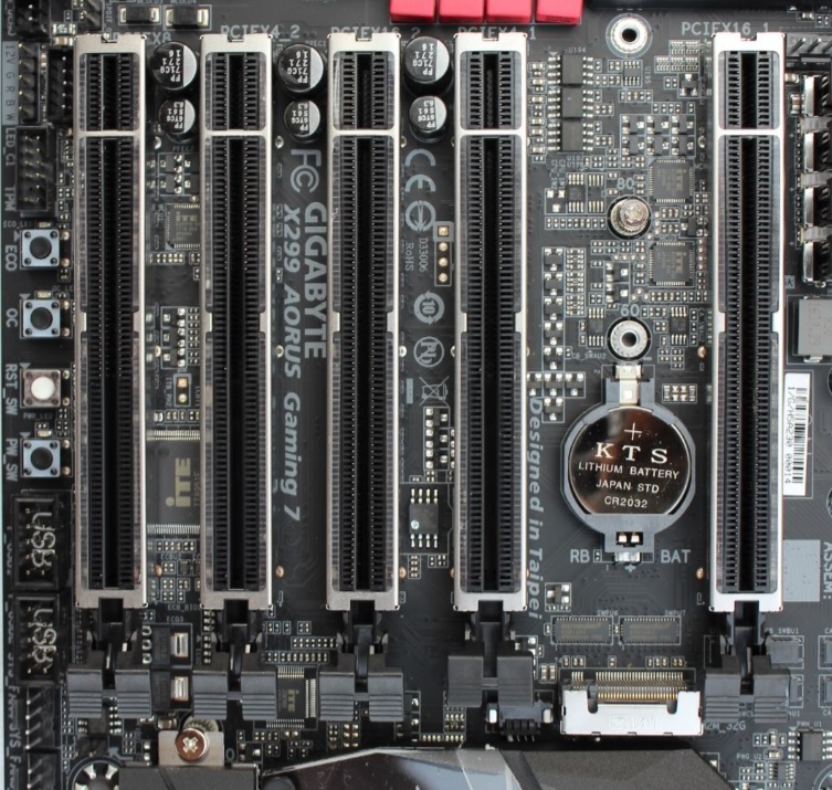
18. 19. M2_1 slot supports 2242/ 2260 /2280 storage devices, M2_2 slot supports 2242/ 2260 /2280/ 22110 storage devices. Intel® Optane™ Memory Ready
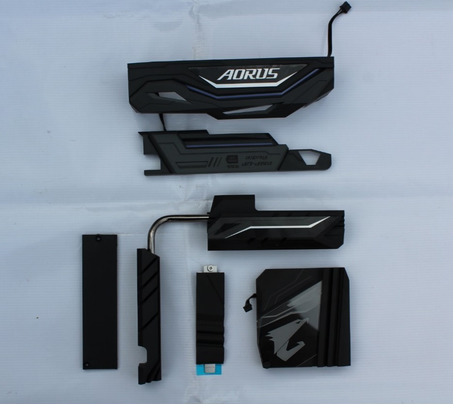
Removing Heat-sinks
Gigabyte used aluminum heatsink in this board with proper thermal pad installed. The chipset heatsink have backlit AORUS logo.
I/O cover is having a separate RGB LED PCB mounted..
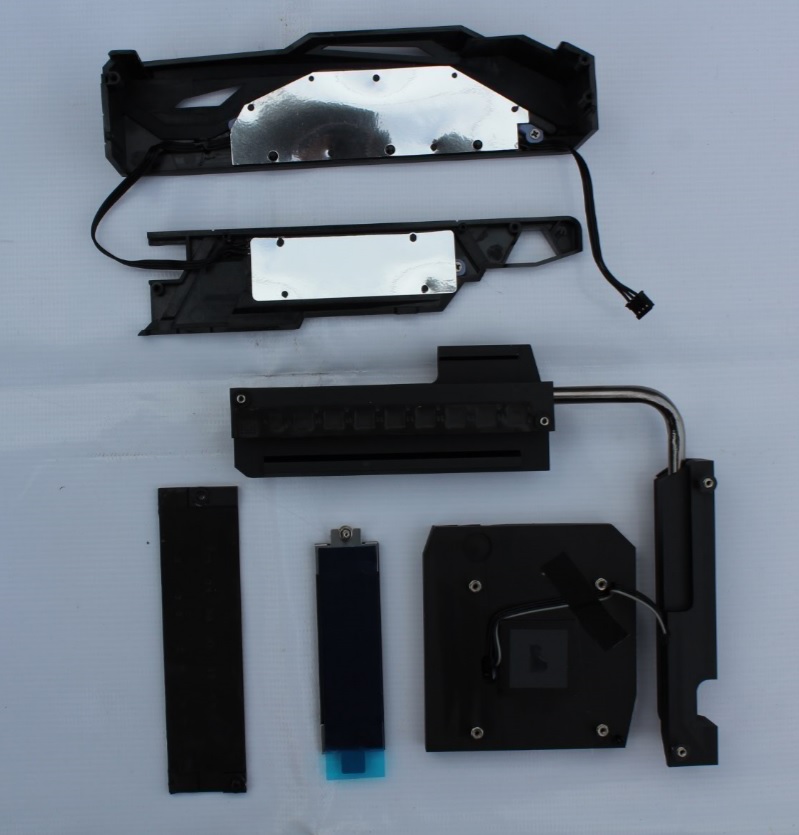
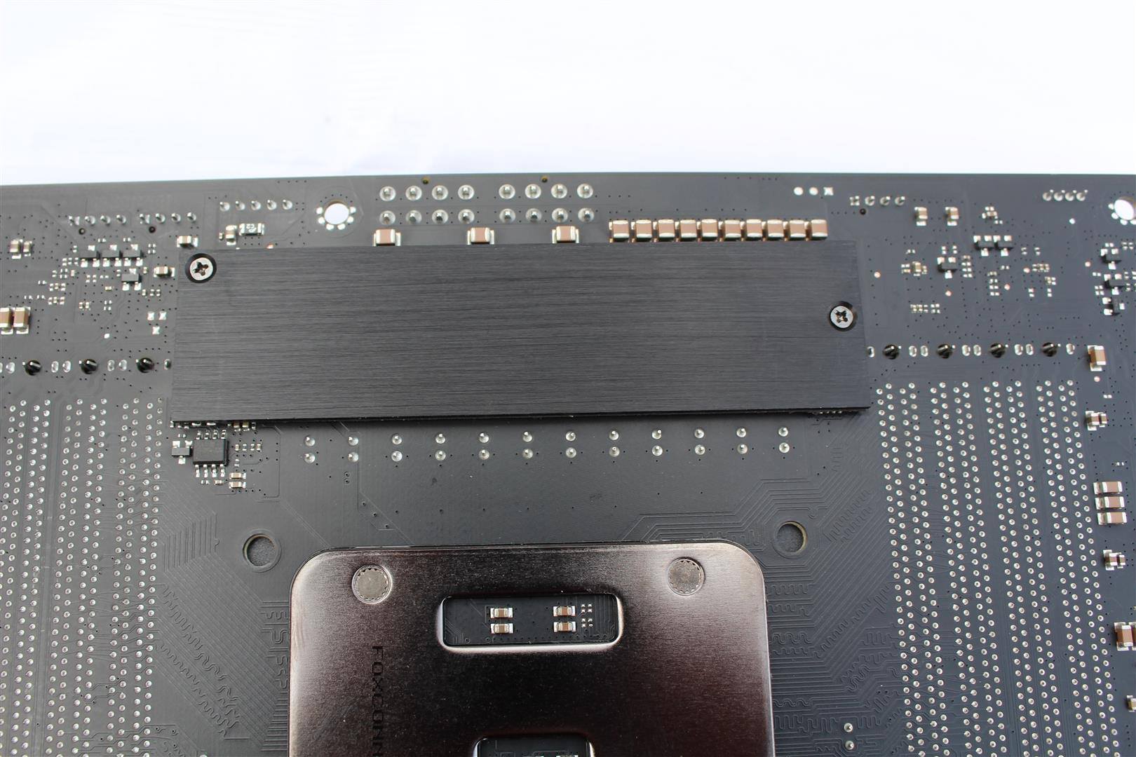
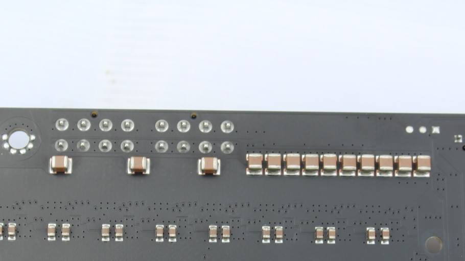
AORUS X299 Gaming 7 Motherboard with bigger VRM heatsink connected via heatpipe increases surface area for better heat dissipation and a thick back plate with proper thermal pad, Two 8-pin power connector with a bank of bypass capacitors on 12v rail. Interesting VRM solution.
Component Layout
Let’s now see what all components GIGABYTE have planned for this board.
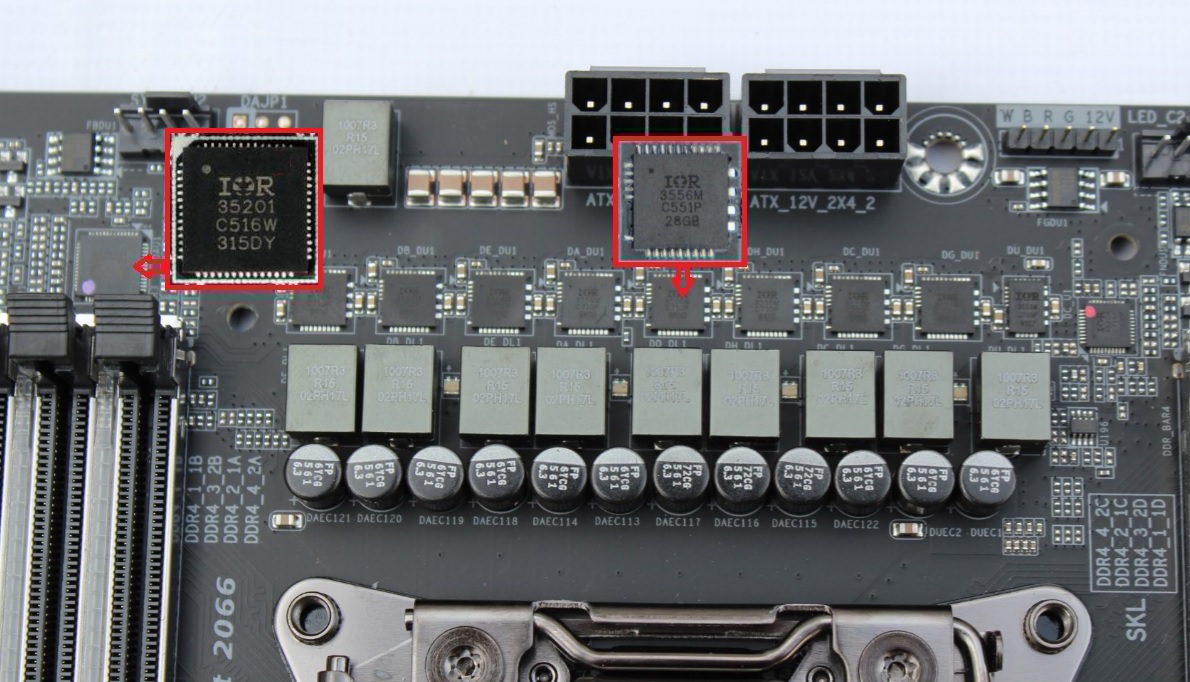
1. 2. 8-phase digital power controlled via International Rectifier IR35201 PWM Controller IC and IR3556M (Integrated PowIRstage) is a synchronous buck gate driver co-packed with a control MOSFET and a synchronous MOSFET with integrated Schottky diode with output current capability of 60A DC each.
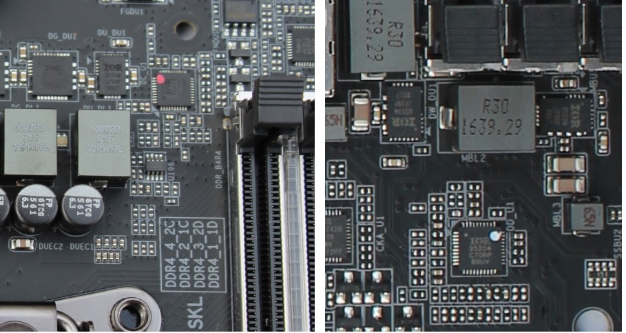
3. Two 2-Phase digital memory power supply section controlled via International Rectifier IR35204 PWM Controller IC and IR3553M MOSFET
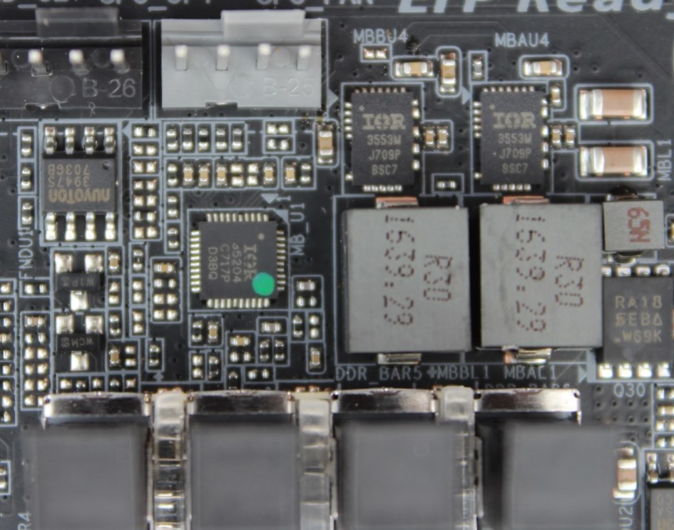
4. These two are VCCSA and VCCIO VRM sections controlled via International Rectifier IR35204 PWM Controller IC and IR3553M MOSFET which only run with a KabyLakeX CPUs. SkylakeX cpu don’t use these VRMs.
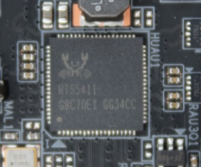
5. Realtek RTS5411 USB3.1 Gen1 Hub chip.
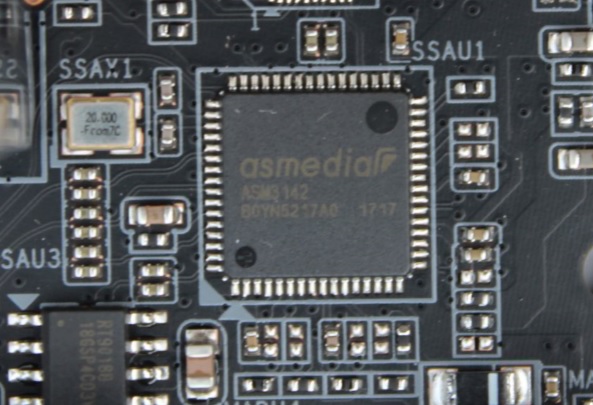
6. 11. ASMedia ASM3142 a USB3.1 Gen2 Controller.
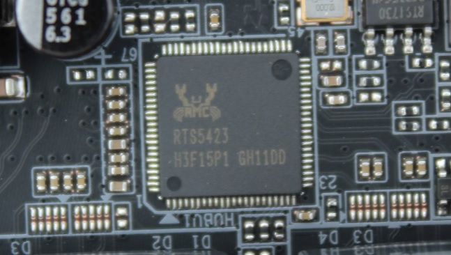
7. Realtek RTS5423 a USB3.1 Gen2 Controller
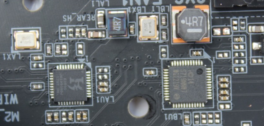
8. 9. Intel and Killer GLan controllers
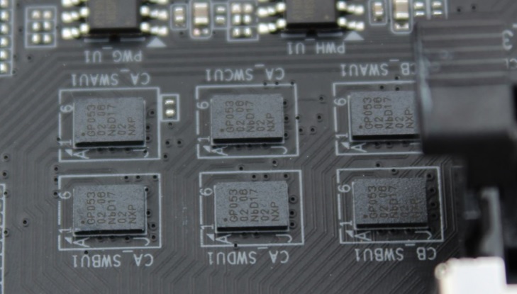
10. NXP Semiconductors CBTL08GP053 a USB Type-C High Performance Crossbar Switch ICs used for Type-C connector interface
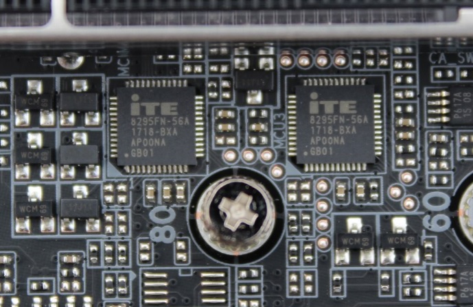
12. 18. iTE 8295FN Microcontrollers used for RGB Fusion with Digital LEDs controlling .
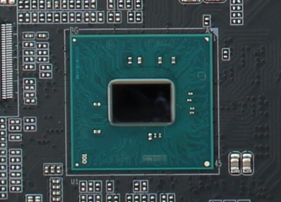
14. Intel X299 Chipset
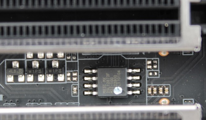
15. Two MX 25L12873F chip for dual UEFI BIOS.
The Intel’s X299 platform had little effect on the high end PC market. Consumers and we all were excited about the new platform, but after the VRM heating issue of X299 motherboards and announcement of the new AMD’s show-stopping 16-core Threadripper CPUs now consumers have a lot to choose from.
Anyway today we are reviewing another X299 motherboard, this time is a Gigabyte product the AORUS X299 Gaming 7 motherboard with RGB Fusion, Digital LED, Triple M.2 with Thermal Guard, ESS SABRE 9018 DAC, Killer DoubleShot™ Pro, Front & rear USB 3.1 Gen 2 Type-C and more.
Now let’s see what this AORUS board have for us.
Features
- Supports Intel® Core™ X-series Processor Family
- Quad Channel Non-ECC Unbuffered DDR4, 8 DIMMs, DDR4400+(OC)
- Intel® Optane™ Memory Ready
- Intel® VROC ready
- ASMedia 3142 USB 3.1 Gen 2 with USB Type-C™ and Type-A
- Front USB 3.1 Gen 2 Header
- 3-Way Graphics Support with Dual Armor and Ultra Durable™ Design
- Server-Class Digital Power Design
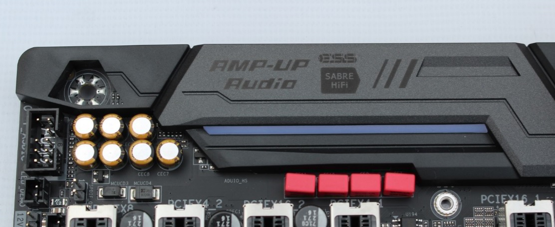
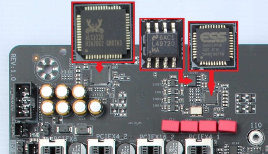
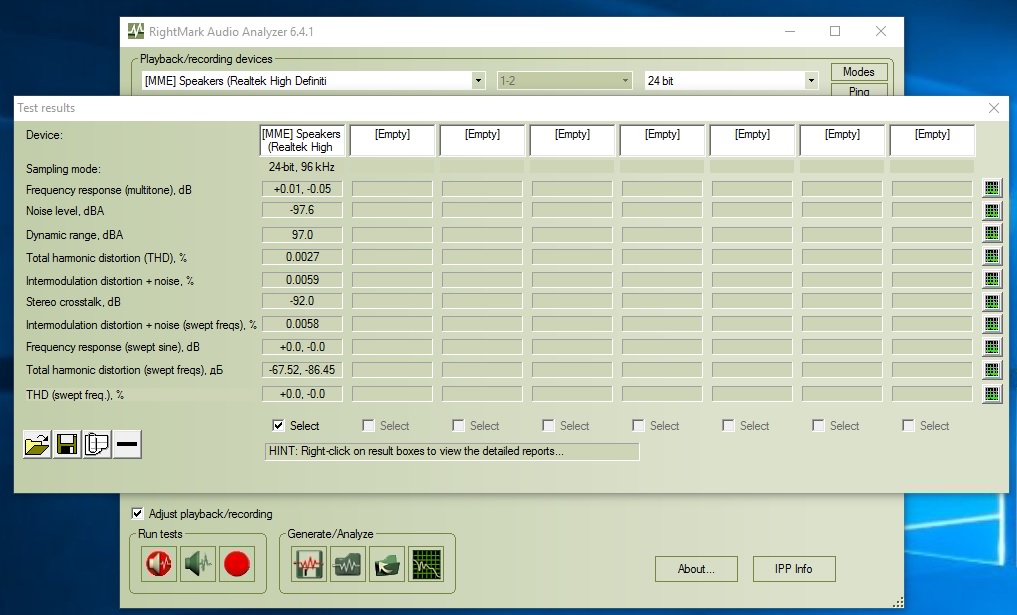
- 121dB SNR AMP-UP Audio with ALC1220 & High-End ESS SABRE 9018 DAC with WIMA audio capacitor
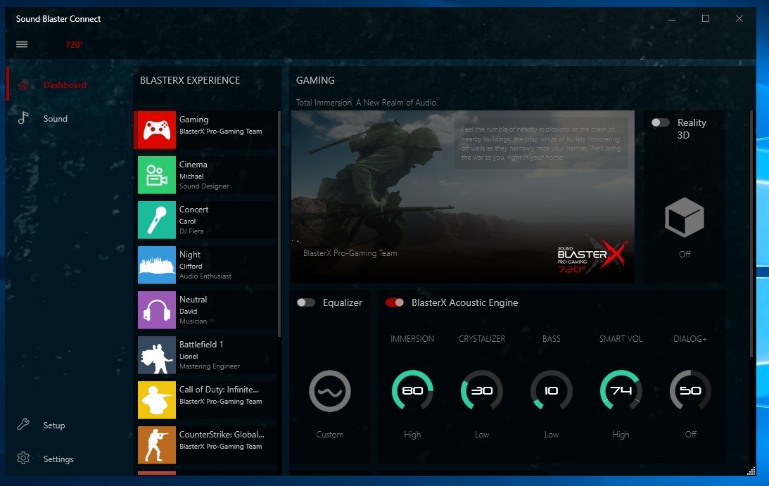
- Sound BlasterX 720°, the top-of-the-line audio engine solution for 4K gaming and entertainment
- Killer DoubleShot™ Pro for the best gaming networking experience possible
- Killer 2x2 802.11ac Wireless – AC 1535
- Intel® GbE LAN Gaming Network
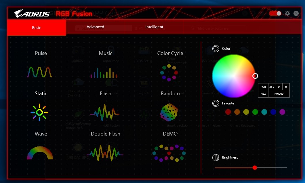
- RGB FUSION with Multi-Zone Digital LED Light Show design, support digital LED & RGB LED strips
- Swappable Overlay for Accent LED
- Smart Fan 5 features Multiple Temperature Sensors and Hybrid Fan Headers with FAN STOP
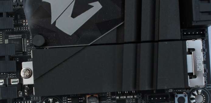
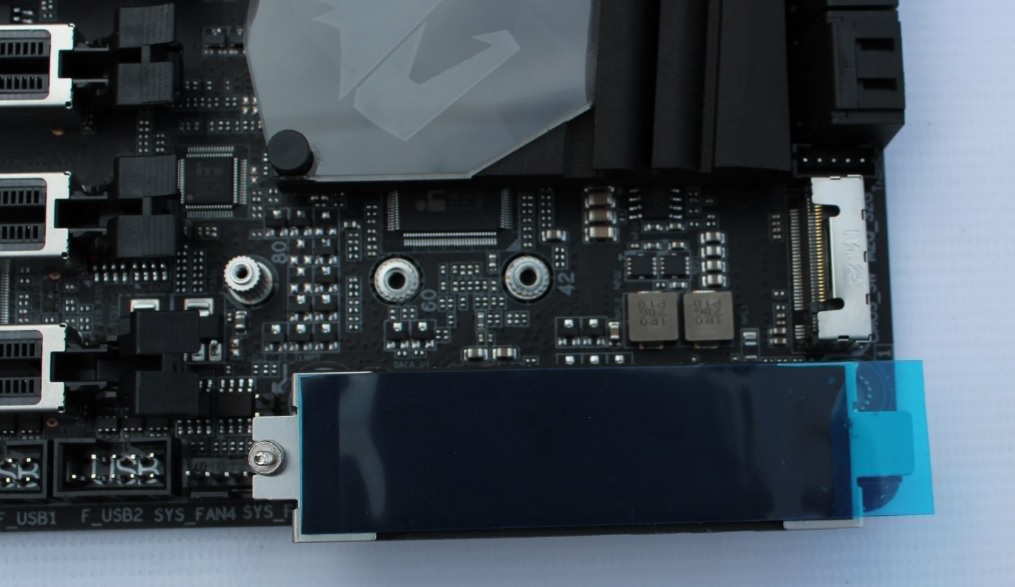
- Triple Ultra-Fast M.2 with PCIe Gen3 x4 interface and Thermal Guard
- NVMe PCIe Gen3 x4 U.2 support by optional adaptor
- USB DAC-UP 2 with Adjustable Voltage
- Precise Digital USB Fuse Design for Stronger Protection
- Anti-Sulfur Resistor Design
- Ultra Durable™ 25KV ESD and 15KV Surge LAN Protection
- Lightning-Fast Intel® Thunderbolt™ 3 AIC Support
- GIGABYTE UEFI DualBIOS™ with Q-Flash Plus USB port
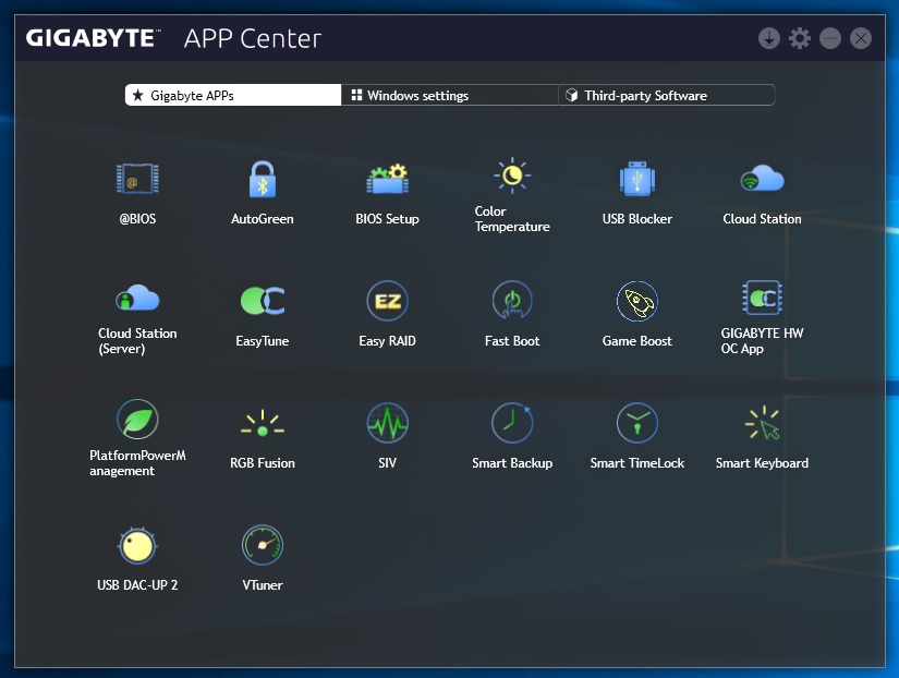
- APP Center Including EasyTune™ and Cloud Station™ Utilities
Specifications
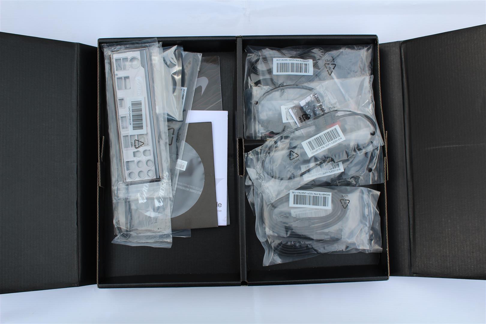
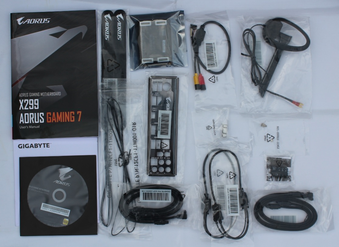
Package
Motherboard comes in a mate gray/orange colour finishing box with a big AORUS logo with motherboard model no. in front At the rear of the box, we find that Gigabyte goes into great detail on the specifications of the motherboard
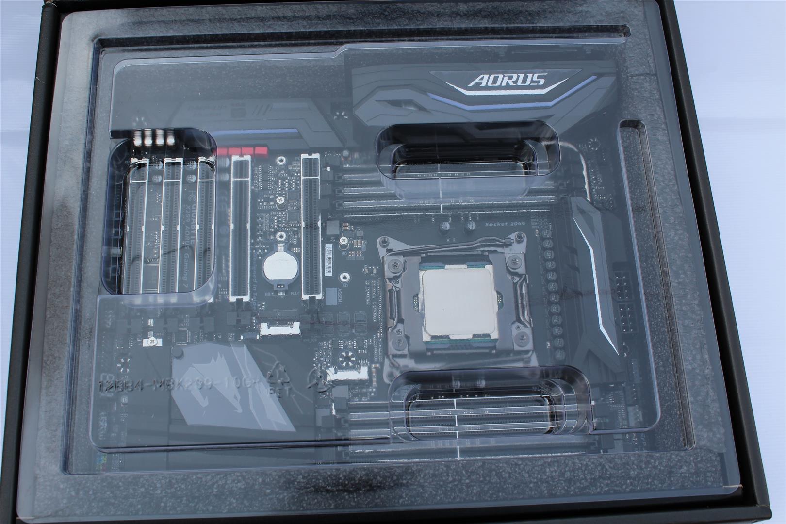
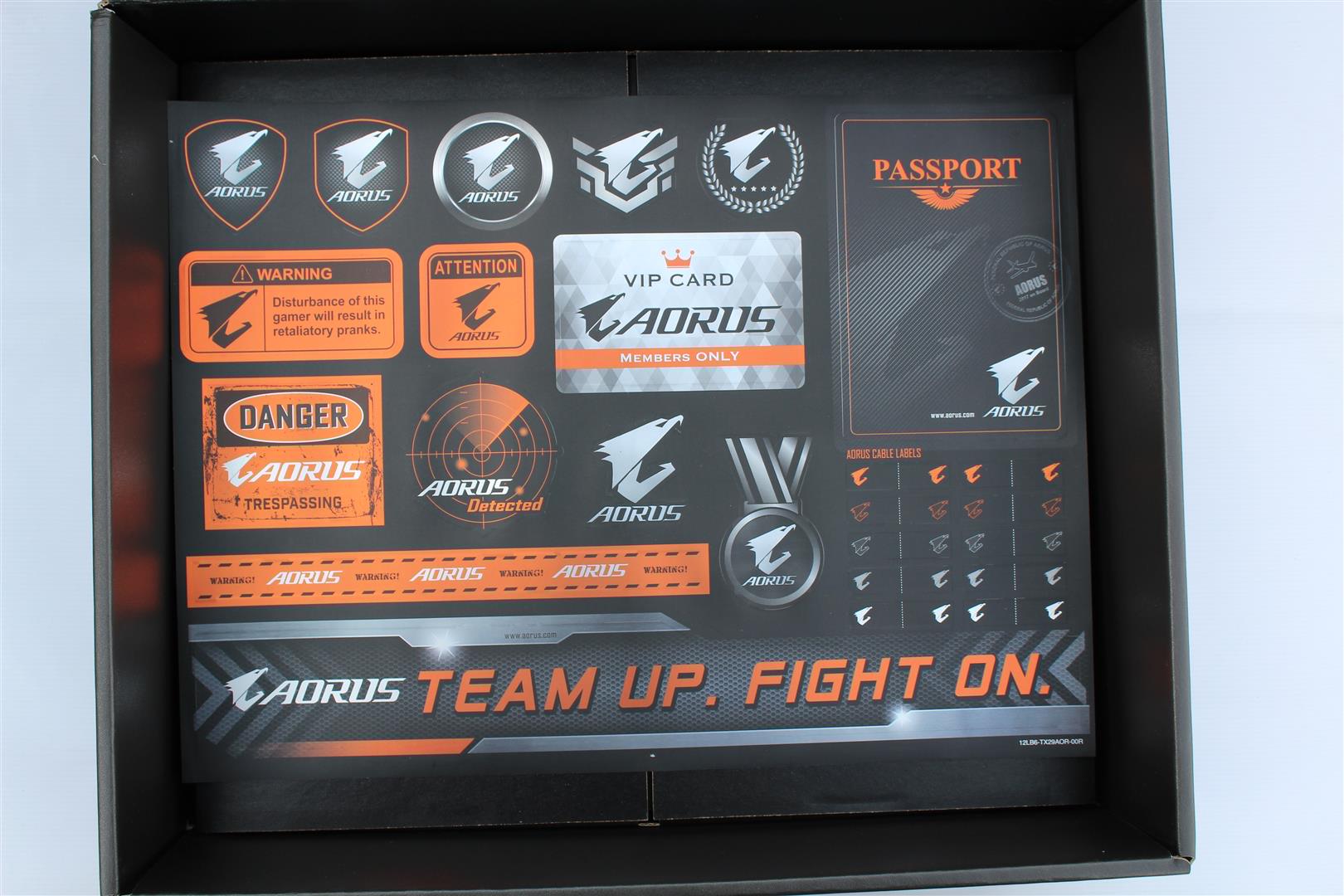
Inside the box
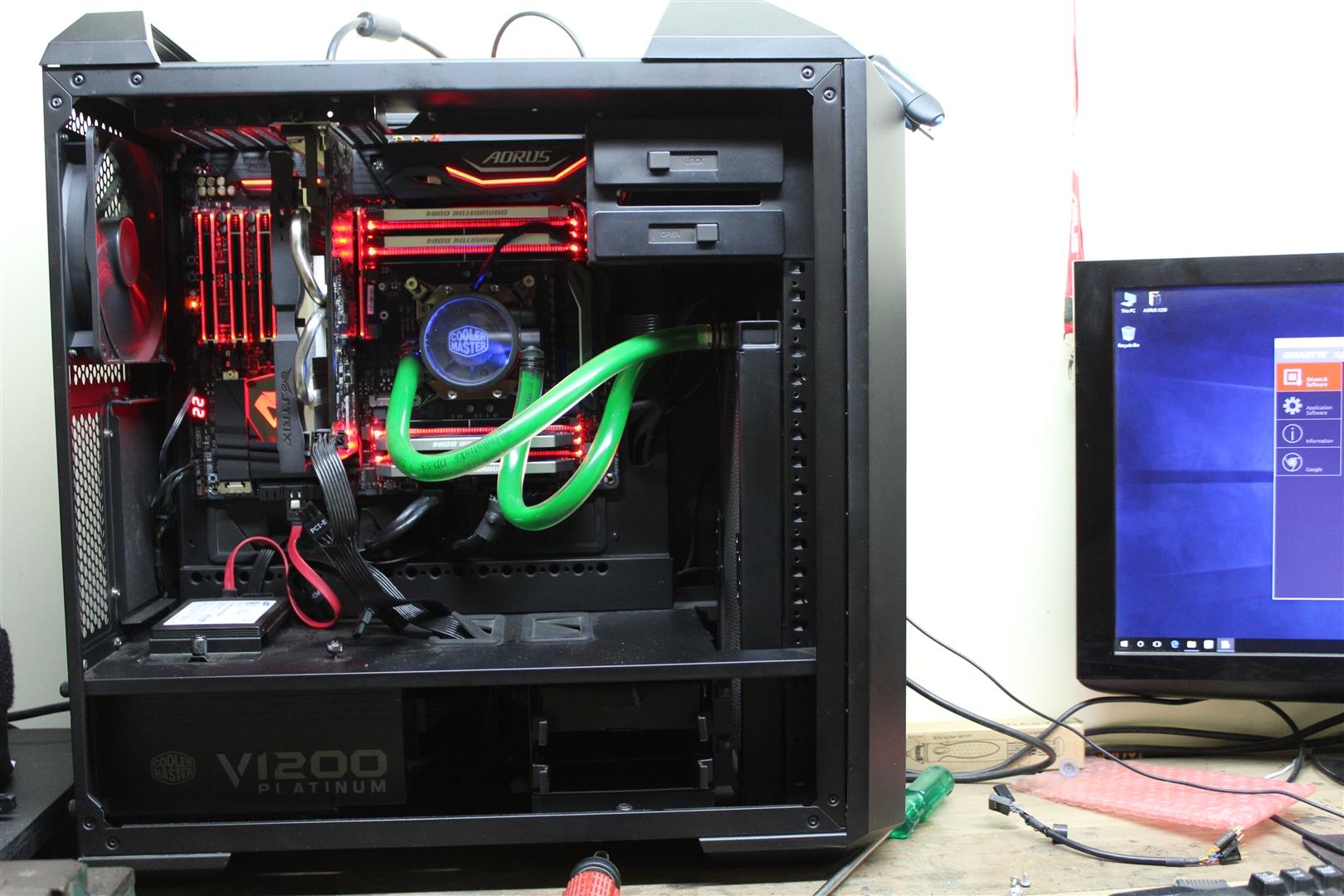
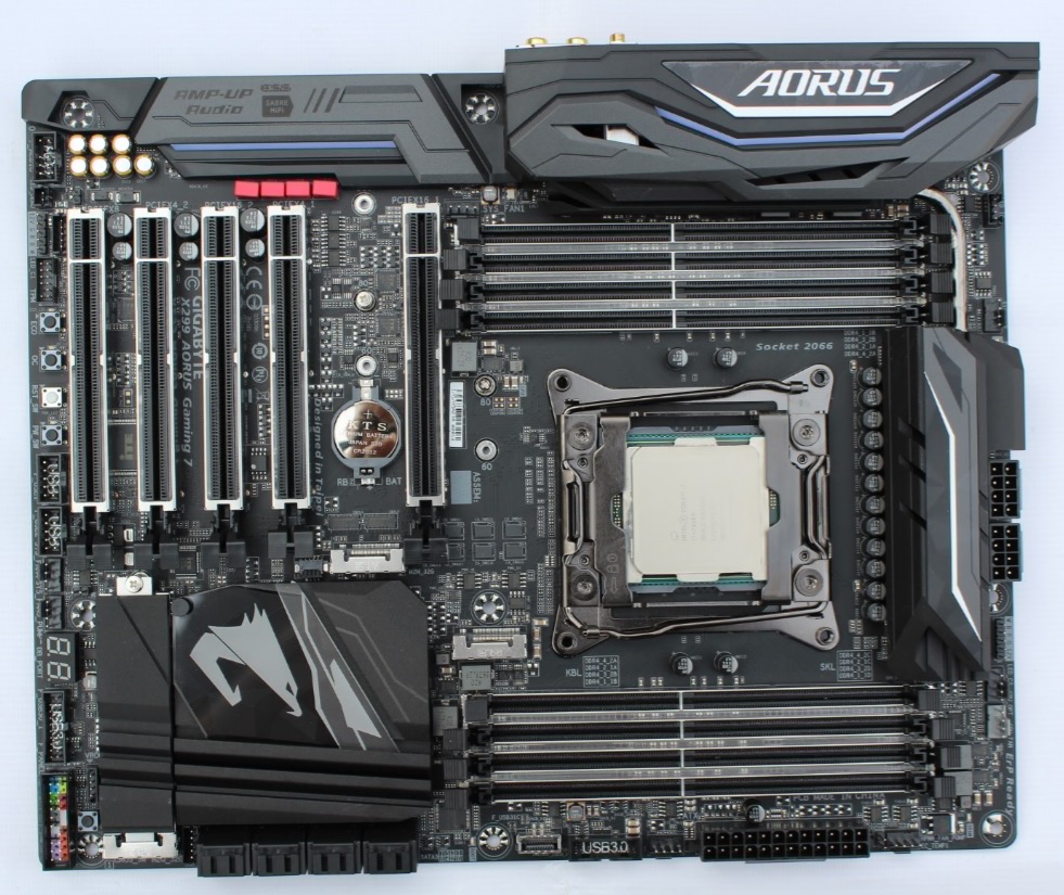
Looks
Board is a solid build in the mate black colour theme.
Layout
Detailed layout of board.
1. New Intel LGA 2066 Socket Supports New Intel Core X-series Processor Family
2. 8 x DDR4 memory slots, support up to 128GB. Quad channel memory architecture
Overclock DDR4 memory frequencies up to 4400MHz.
3. ATX Power connector (24-pin EATXPWR)
4. 2 x ATX CPU Power Connector (8-pin + 8 Pin ATX12V).
5. Back I/O ports : PS/2 keyboard/mouse port, USB Type-C™ port, with USB 3.1 Gen 2 support, 4 x USB 3.1 Gen 2 Type-A ports (red), 4 x USB 3.1 Gen 1 ports, 2 x RJ-45 ports, 2 x MMCX antenna connectors (2T2R), optical S/PDIF Out connector, 5 x audio jacks (Center/Subwoofer Speaker Out, Rear Speaker Out, Line In, Line Out, Mic In))
6. Fan Connectors : 1 x CPU fan header, 1 x water cooling CPU fan header, 4 x system fan headers, 1 x system fan/water cooling pump header, 1 x 3 Amp fan/water cooling pump header
7. Debug Code display.
8. 9.Front 2 X USB 3.1 Gen1 connectors and USB 3.1 Gen2 Type-C port.
10.8 x SATA 6Gb/s connectors.
11. Front Panel Connector
12. 2 x USB 2.0 Connectors
13. Power button, reset button, ECO button and OC button
14. Trusted Platform Module (TPM) header (2x6 pin, for the GC-TPM2.0_S module only)
15. 2 x RGB (RGBW) LED strip extension cable headers
16. Front panel audio connector
17. Expansion Slots : 2 x PCI Express x16 slots, running at x16 (PCIEX16_1, PCIEX16_2), 1 x PCI Express x16 slot, running at x8 (PCIEX8), 2 x PCI Express x16 slots, running at x4 (PCIEX4_1, PCIEX4_2)
18. 19. M2_1 slot supports 2242/ 2260 /2280 storage devices, M2_2 slot supports 2242/ 2260 /2280/ 22110 storage devices. Intel® Optane™ Memory Ready
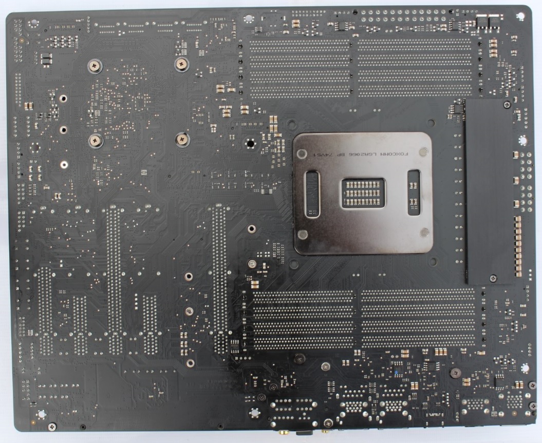
Removing Heat-sinks
Gigabyte used aluminum heatsink in this board with proper thermal pad installed. The chipset heatsink have backlit AORUS logo.
I/O cover is having a separate RGB LED PCB mounted..
AORUS X299 Gaming 7 Motherboard with bigger VRM heatsink connected via heatpipe increases surface area for better heat dissipation and a thick back plate with proper thermal pad, Two 8-pin power connector with a bank of bypass capacitors on 12v rail. Interesting VRM solution.
Component Layout
Let’s now see what all components GIGABYTE have planned for this board.
1. 2. 8-phase digital power controlled via International Rectifier IR35201 PWM Controller IC and IR3556M (Integrated PowIRstage) is a synchronous buck gate driver co-packed with a control MOSFET and a synchronous MOSFET with integrated Schottky diode with output current capability of 60A DC each.
3. Two 2-Phase digital memory power supply section controlled via International Rectifier IR35204 PWM Controller IC and IR3553M MOSFET
4. These two are VCCSA and VCCIO VRM sections controlled via International Rectifier IR35204 PWM Controller IC and IR3553M MOSFET which only run with a KabyLakeX CPUs. SkylakeX cpu don’t use these VRMs.
5. Realtek RTS5411 USB3.1 Gen1 Hub chip.
6. 11. ASMedia ASM3142 a USB3.1 Gen2 Controller.
7. Realtek RTS5423 a USB3.1 Gen2 Controller
8. 9. Intel and Killer GLan controllers
10. NXP Semiconductors CBTL08GP053 a USB Type-C High Performance Crossbar Switch ICs used for Type-C connector interface
12. 18. iTE 8295FN Microcontrollers used for RGB Fusion with Digital LEDs controlling .
14. Intel X299 Chipset
15. Two MX 25L12873F chip for dual UEFI BIOS.