Have a mouse you like a lot but it is permanently hooked up to your PC and you're lazy to remove it everytime you want to switch devices?
The easy solution - Get a wireless mouse that is similar.
The difficult solution - Convert the mouse to USB-C and remove just the mouse, leaving just the cable hanging. A caveat though is that, with the standard USB-C breakout boards available, you will not be able to use USB C-C cables until you add a resistor, which is a tad difficult since only few boards have the pads designed for such a case and even then, they are too large to accomodate a regular resistor that you will be able to source easily. It is doable, but you need to be a little proficient in soldering.
This is how I did the difficult solution for a mouse i recently bought from @mehimdumb_7t for dirt cheap because the encoder was failing. He was kind enough to even provide a guide on how to change the encoder and gave me ideas on where I could source them.
The mouse in question is a Wired ROG Gladius III. The same mouse comes as a wireless version, but isn't available in the Indian market. I have a desk that I use for multiple purposes and hence like it to be clean when I'm not using my computer but when needed, ready to use with minimal difficulty. Hence this mod.
Also kudos to ASUS for designing the mouse to be extremely user-repairable.
A little about USB (Holds true until USB 2.0, USB 3.0 has it's own myriad of points and is irrelevant here.)
Most USB devices work at 5V. All USB power sources by default provide 5V. It is only after Power Delivery was introduced and the concept of negotiating power between the sink (The device getting power) and source that this rule was broken.
In our case and for the case of most non-storage peripherals (Mice, Keyboards, Printers, Joysticks) it is USB 2.0 that is used widely. The bandwidth of USB 2.0 (480Mbps) is more than sufficient for these use cases. This makes our job easier, since we only need to worry about 4 wires (or 2 pairs) of wires.
What are they?
1. The Power Wire pair - They are the Positive and negative wires (5V and Ground).
2. The Data Wire pair - They are the Data + and Data - wires ( D+ and D-).
Sometimes in addition to these wires, there is also an exposed bare metal wire sheath that covers these 4 wires. This is also a ground wire and is connected to the ground pin but only on the source side and not the sink. The reason this sheath is present is to prevent interference by other radiating signals (all wires act as antennae) resulting in degraded performance.

Cross Section of a USB 2.0 wire.
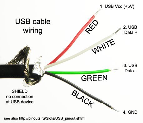
By convention, the red wire is the positive wire, the black is the ground, the white is the Data + and the Green is the Data - . However, there is no standard and this may vary between manufacturers.
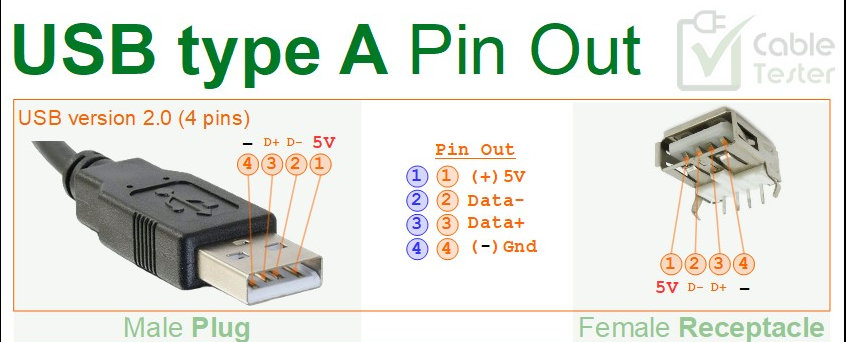
To identify which wire is which, we will have to use a multimeter set to continuity mode and test the wire from the USB-A plug to the cut end. Below is a diagram showing which pins are which signals. This is standard across all connectors.
Now let's start with the conversion.
Here's what you need:
1. The mouse you want to convert.
2. A USB-C female breakout board. Get the small ones which have just 4 pads exposed. (V+, Gnd, D+ and D-)
3. A multimeter.
4. A soldering iron, some solder wire and solder flux.
5. A hot glue gun or atleast a hot glue stick.
6. It would be nice to have some other tools like a 3rd hand or forceps to help you hold the wire while you solder it in place. It is doable even otherwise, but this makes your job much easier.
7. A USB-C male breakout board. (If you intend to use the wire you have cut as a USB A-C cable)
First open up the mouse. Most mice have 1 or 2 screws on the bottom that can be easily accessed and removed. Once removed, you may need to slide the mouse a certain way to remove the plastic locking clips. Take care and do this slowly, you don't want to break the retainer clips. While you can attach them again with QuikFix, that is a problem that you do not want to have on your hands.
Once you have opened up the mouse, you should be able to see something like this:
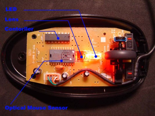
At the bottom of the picture, you're able to see a black wire that splits into 4 smaller wires which are connected to a PCB. This is the USB wire. You will be able to trace it to a small hole through which it leaves the body of the mouse. Now, you need to cut the wire an inch outside the hole (Out of the body of the mouse). The reason for this is that we want to have some slack with the cable while also giving us enough room to correct any mistakes we may have made.
Once the wire is cut, we need to remove the PCB from the body of the mouse. They are either held in by screws or by friction. Check for any screws, if you're unable to find any, then they are probably held in by friction (like the example above). When removing take care not to damage the sensor below the PCB. It is of 2 parts, the sensor itself and a piece of plastic lens. Both of these are important, take care you don't scratch them by mistake.
Next, we need to make a hole large enough to fit a USB-C male plug. This can be achieved by making the small hole through which the original wire passed larger such that it is easy to accomodate a USB-C plug. However, you can think of other innovative ways to make the hole.
Now that you have made the hole, place the female USB-C adapter such that it sits flush with the body or juts out just a little bit. This depends on the amount of space available inside the mouse and your aesthetic appeal.
Now, we need to solder the wires to the USB-C connector. If your mouse manufacturer likes you, he may make your job easier by printing the legends for the wires on the PCB of the mouse near the connector itself and all you need to do is match and solder the wires correctly.
However, if nothing is marked on the wires, you can still find out how, just that it will take some extra time. You need to probe the USB-A connector against the cut end of the wire to find out which wire is which. For reference,use the image linked above. and again here below Do this stage patiently. It's okay if you make sure twice instead of just once. We don't want a blown mouse or even worse, a blown computer. (A very real possibility when you mix up wires)
Once you've identified the wires, match them up to the corresponding pads on the female breakout board and solder them. Once this is done, your mouse is essentially ready. You can now test that everything works by connecting a USB A to USB C cable to the breakout board and checking that the mouse works as expected.
Now that we've confirmed that everything is working as expected, we need to fix the USB C breakout board such that it is sturdy enough to not move with repeated insertion cycles. We also need to make sure that the wires or the pads of the breakout board are not in contact with the underside of the PCB. Both of this can be achieved by using a hot glue gun. Place a nice large drop of hot glue on the base of the plastic on top of which you will place the breakout board. Make sure of the alignment. Once the glue cools a bit, place another large drop on the top of the board, making sure it covers all exposed pins. Use a toothpick or something similar to spread the glue if needed. Let it dry. Now try repeatedly inserting a USB cable to make sure that you've done a good job and it'll hold up for a long time.
Finally put the mouse back together and voila, you now have a mouse that is USB-C compatible.
As for the cable, you can either throw it, or if you like too much, you can attach a male breakout board to the cut end and use it as a USB A to USB C cable. The soldering is similar to the female breakout board.
However, the hot glue part will need to be extra reinforced such that the cable is able to put up with high amounts of abuse. Remember, you always hold the male end of the cable when plugging/unplugging and that is where most force is exerted.
These are the images of the mouse I modified.
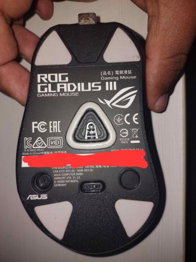
As seen, the USB-C female plug is jutting out on mine, but it doesn't affect the functioning of the mouse in any way and I am more function over form, hence this doesn't disturb me.
The USB-C breakout board with the base PCB (The mouse wheel is removed in this picture)
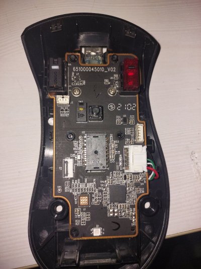
The USB-C breakout breakout board fixed with hot glue.
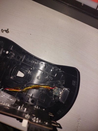
The yellow tape is Kapton tape. It acts as a insulator between the base PCB and the wires, preventing short circuits. This came standard with the mouse. You can add this if you want to, but the tape is extremely costly.
Thank you for reading through my boring guide on how to convert a wired USB mouse to USB-C.
Cheers.
The easy solution - Get a wireless mouse that is similar.
The difficult solution - Convert the mouse to USB-C and remove just the mouse, leaving just the cable hanging. A caveat though is that, with the standard USB-C breakout boards available, you will not be able to use USB C-C cables until you add a resistor, which is a tad difficult since only few boards have the pads designed for such a case and even then, they are too large to accomodate a regular resistor that you will be able to source easily. It is doable, but you need to be a little proficient in soldering.
This is how I did the difficult solution for a mouse i recently bought from @mehimdumb_7t for dirt cheap because the encoder was failing. He was kind enough to even provide a guide on how to change the encoder and gave me ideas on where I could source them.
The mouse in question is a Wired ROG Gladius III. The same mouse comes as a wireless version, but isn't available in the Indian market. I have a desk that I use for multiple purposes and hence like it to be clean when I'm not using my computer but when needed, ready to use with minimal difficulty. Hence this mod.
Also kudos to ASUS for designing the mouse to be extremely user-repairable.
A little about USB (Holds true until USB 2.0, USB 3.0 has it's own myriad of points and is irrelevant here.)
Most USB devices work at 5V. All USB power sources by default provide 5V. It is only after Power Delivery was introduced and the concept of negotiating power between the sink (The device getting power) and source that this rule was broken.
In our case and for the case of most non-storage peripherals (Mice, Keyboards, Printers, Joysticks) it is USB 2.0 that is used widely. The bandwidth of USB 2.0 (480Mbps) is more than sufficient for these use cases. This makes our job easier, since we only need to worry about 4 wires (or 2 pairs) of wires.
What are they?
1. The Power Wire pair - They are the Positive and negative wires (5V and Ground).
2. The Data Wire pair - They are the Data + and Data - wires ( D+ and D-).
Sometimes in addition to these wires, there is also an exposed bare metal wire sheath that covers these 4 wires. This is also a ground wire and is connected to the ground pin but only on the source side and not the sink. The reason this sheath is present is to prevent interference by other radiating signals (all wires act as antennae) resulting in degraded performance.
Cross Section of a USB 2.0 wire.

By convention, the red wire is the positive wire, the black is the ground, the white is the Data + and the Green is the Data - . However, there is no standard and this may vary between manufacturers.
To identify which wire is which, we will have to use a multimeter set to continuity mode and test the wire from the USB-A plug to the cut end. Below is a diagram showing which pins are which signals. This is standard across all connectors.

Now let's start with the conversion.
Here's what you need:
1. The mouse you want to convert.
2. A USB-C female breakout board. Get the small ones which have just 4 pads exposed. (V+, Gnd, D+ and D-)
3. A multimeter.
4. A soldering iron, some solder wire and solder flux.
5. A hot glue gun or atleast a hot glue stick.
6. It would be nice to have some other tools like a 3rd hand or forceps to help you hold the wire while you solder it in place. It is doable even otherwise, but this makes your job much easier.
7. A USB-C male breakout board. (If you intend to use the wire you have cut as a USB A-C cable)
First open up the mouse. Most mice have 1 or 2 screws on the bottom that can be easily accessed and removed. Once removed, you may need to slide the mouse a certain way to remove the plastic locking clips. Take care and do this slowly, you don't want to break the retainer clips. While you can attach them again with QuikFix, that is a problem that you do not want to have on your hands.
Once you have opened up the mouse, you should be able to see something like this:

At the bottom of the picture, you're able to see a black wire that splits into 4 smaller wires which are connected to a PCB. This is the USB wire. You will be able to trace it to a small hole through which it leaves the body of the mouse. Now, you need to cut the wire an inch outside the hole (Out of the body of the mouse). The reason for this is that we want to have some slack with the cable while also giving us enough room to correct any mistakes we may have made.
Once the wire is cut, we need to remove the PCB from the body of the mouse. They are either held in by screws or by friction. Check for any screws, if you're unable to find any, then they are probably held in by friction (like the example above). When removing take care not to damage the sensor below the PCB. It is of 2 parts, the sensor itself and a piece of plastic lens. Both of these are important, take care you don't scratch them by mistake.
Next, we need to make a hole large enough to fit a USB-C male plug. This can be achieved by making the small hole through which the original wire passed larger such that it is easy to accomodate a USB-C plug. However, you can think of other innovative ways to make the hole.
Now that you have made the hole, place the female USB-C adapter such that it sits flush with the body or juts out just a little bit. This depends on the amount of space available inside the mouse and your aesthetic appeal.
Now, we need to solder the wires to the USB-C connector. If your mouse manufacturer likes you, he may make your job easier by printing the legends for the wires on the PCB of the mouse near the connector itself and all you need to do is match and solder the wires correctly.
However, if nothing is marked on the wires, you can still find out how, just that it will take some extra time. You need to probe the USB-A connector against the cut end of the wire to find out which wire is which. For reference,use the image linked above. and again here below Do this stage patiently. It's okay if you make sure twice instead of just once. We don't want a blown mouse or even worse, a blown computer. (A very real possibility when you mix up wires)
Once you've identified the wires, match them up to the corresponding pads on the female breakout board and solder them. Once this is done, your mouse is essentially ready. You can now test that everything works by connecting a USB A to USB C cable to the breakout board and checking that the mouse works as expected.
Now that we've confirmed that everything is working as expected, we need to fix the USB C breakout board such that it is sturdy enough to not move with repeated insertion cycles. We also need to make sure that the wires or the pads of the breakout board are not in contact with the underside of the PCB. Both of this can be achieved by using a hot glue gun. Place a nice large drop of hot glue on the base of the plastic on top of which you will place the breakout board. Make sure of the alignment. Once the glue cools a bit, place another large drop on the top of the board, making sure it covers all exposed pins. Use a toothpick or something similar to spread the glue if needed. Let it dry. Now try repeatedly inserting a USB cable to make sure that you've done a good job and it'll hold up for a long time.
Finally put the mouse back together and voila, you now have a mouse that is USB-C compatible.
As for the cable, you can either throw it, or if you like too much, you can attach a male breakout board to the cut end and use it as a USB A to USB C cable. The soldering is similar to the female breakout board.
However, the hot glue part will need to be extra reinforced such that the cable is able to put up with high amounts of abuse. Remember, you always hold the male end of the cable when plugging/unplugging and that is where most force is exerted.
These are the images of the mouse I modified.

As seen, the USB-C female plug is jutting out on mine, but it doesn't affect the functioning of the mouse in any way and I am more function over form, hence this doesn't disturb me.
The USB-C breakout board with the base PCB (The mouse wheel is removed in this picture)

The USB-C breakout breakout board fixed with hot glue.

The yellow tape is Kapton tape. It acts as a insulator between the base PCB and the wires, preventing short circuits. This came standard with the mouse. You can add this if you want to, but the tape is extremely costly.
Thank you for reading through my boring guide on how to convert a wired USB mouse to USB-C.
Cheers.


