A Never Ending Back Story:
About two and a half years ago, I bought an inverter that needed four batteries running at 48V:
https://techenclave.com/threads/wtb-sinewave-ups-inverter-so-need-suggestions.198174/#post-2269678
The inverter was paired with four Amaron Quanta batteries, this was a decision I made — I thought the were really cool looking, colour matched the inverter nicely, didn’t need any maintenance and I later learned that this kind of lead acid battery (vrla/agm) doesn’t have any corrosion on the battery terminals as you would see in flooded lead acid batteries. I also found out that there are detailed datasheets with charge/discharge curves (with Peukert’s law taken into account).
I also did the installation on my own, and I never did something like this before. How hard could it be? Turns out, there’s more to this than just wiring up four batteries in series. The terminals should be scrubbed down until the copper is nice and shiny, the batteries should be pre-charged individually for a day each, and it’s a good idea to check to see if the batteries are from the same batch.
I didn’t do any of that and I didn’t notice that one of the four batteries did not have a serial number that was sequential with the others. It was also missing the Q sticker on top of the battery, which was present on the other three batteries. For whatever reason, this battery was different — either a customer return or exchanged/forgotten stock.
And two years later that battery is now dead with a shorted cell inside (12V lead acid batteries have six cells inside of them). Run time has come down from a few hours to a few minutes as a result. Because of the shorted cell, the other batteries suffered and never charged fully (a lead acid battery with a shorted cell pulls more voltage, which prevents other batteries from getting a full charge).
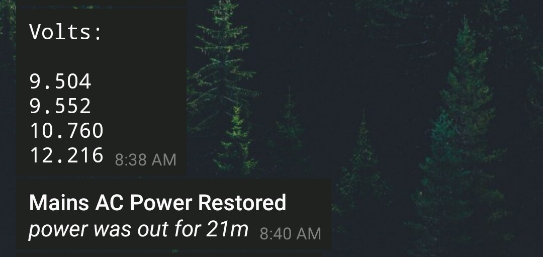
Had I checked the voltages regularly, or had something that would report voltages, this issue might have been caught before irreversible damage was done to the other batteries:
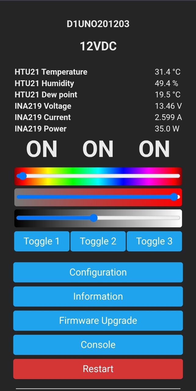
After testing the battery voltages under load with a multimeter (and discovering the dead battery), I put together a few simple wi-fi monitors using ESP8266 controllers running Tasmota connected to INA219 current/voltage sensors and recorded these readings:
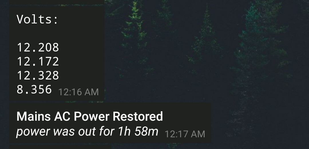
The dead battery fell to ~8V with a simple 25w load.
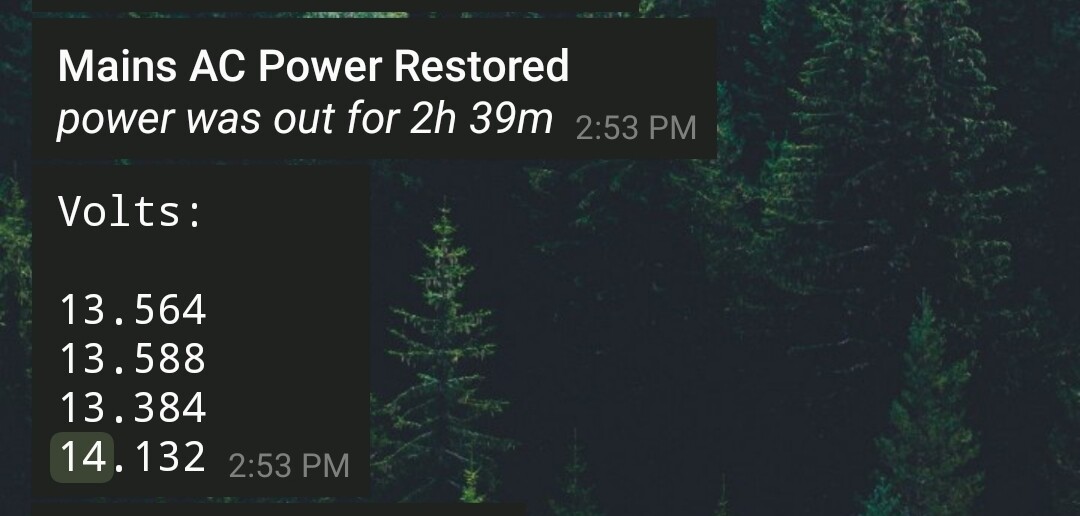
And when charging, it pulled over 14V, preventing the other batteries from charging fully.
[HR][/HR]
[HR][/HR]
[HR][/HR]
So here in this guide, I’m rebuilding those battery monitors into a more permanent and usable version. One of the philosophies that has evolved in my DIY projects is not using any custom/bespoke PCBs/hardware, everything needs to be modular and easily available/replaceable. The need to get something working quickly again after a failure far outweighs any benefits a custom solution might have.
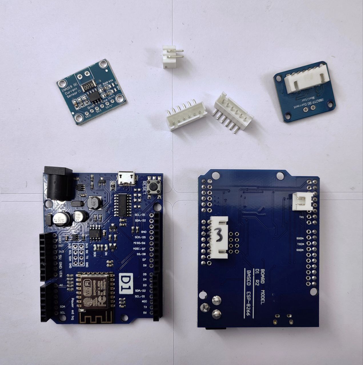
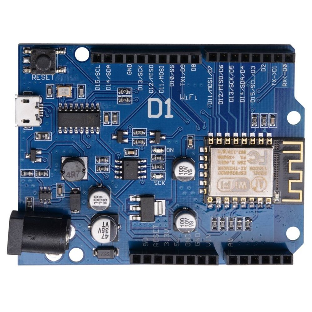
I chose the Wemos D1 R2 ESP8266 module since it can be powered directly from the battery that’s being measured. It also had unpopulated pinouts that I attached JST 2.5mm right angle connectors to for easier wiring. We’re interested in five lines from the module, two for I2C and two for VIN and GND and a 3.3V to power the INA219. The connectors and wires were purchased from Sunrom:
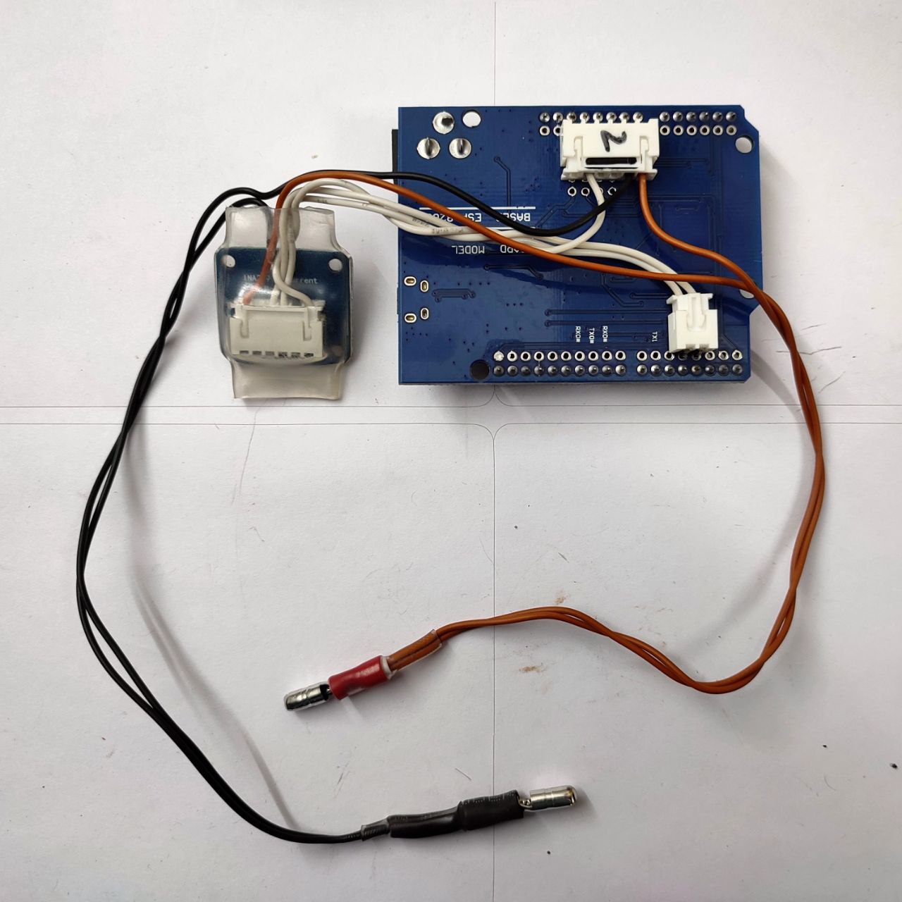
I used 10cm pre-crimped wires to connect to the INA219 module and 30cm wires to connect to the battery. There are two wires coming from each terminal of the battery to get the most accurate readings possible, without the voltage drop you might see if I were to measure the VIN voltage on the ESP8266 board instead. The INA219 modules have a 4mV resolution, which is more than what we need (100mV would’ve been enough). The INA219 modules are covered in transparent heatshrink, and there’s heatshrink on the bullet connectors as well (transparent on the positive line, black + transparent on the negative line). These are the bullet connectors:
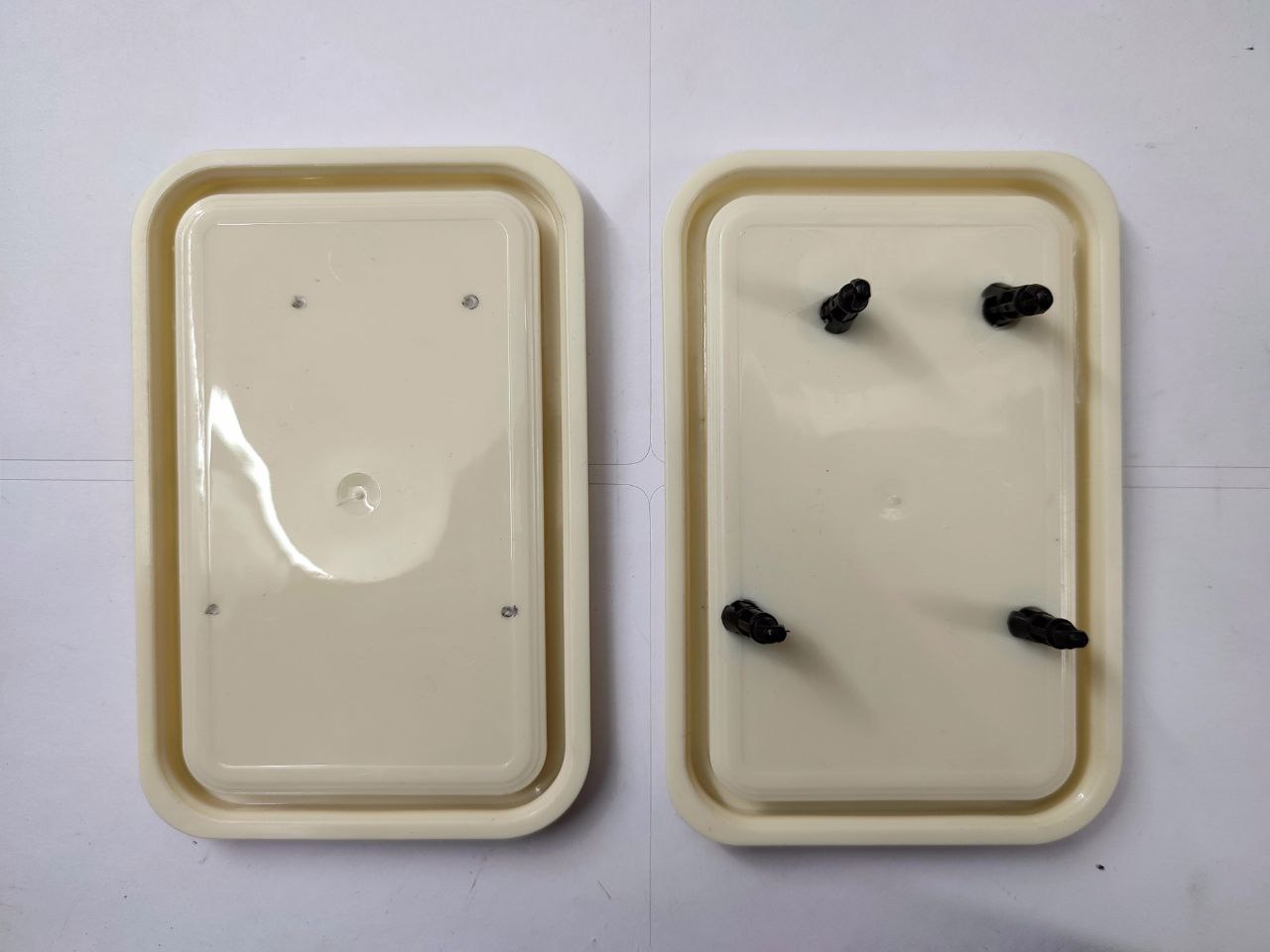
The ESP8266 modules will be housed in a few generic 200ml food containers. Holes were marked, drilled out to 5mm and these snap fit PCB spacers were installed:
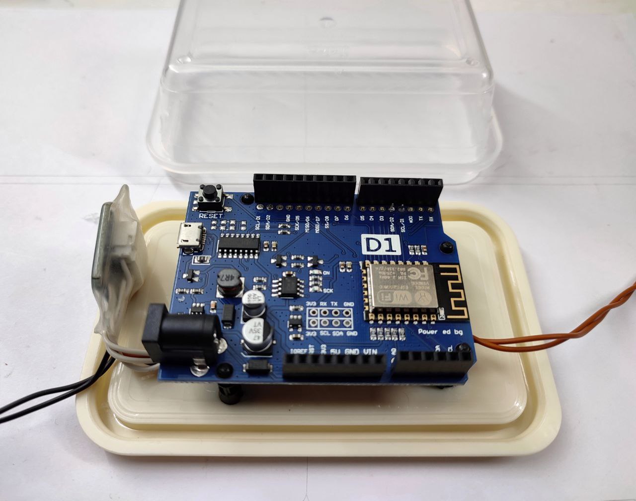
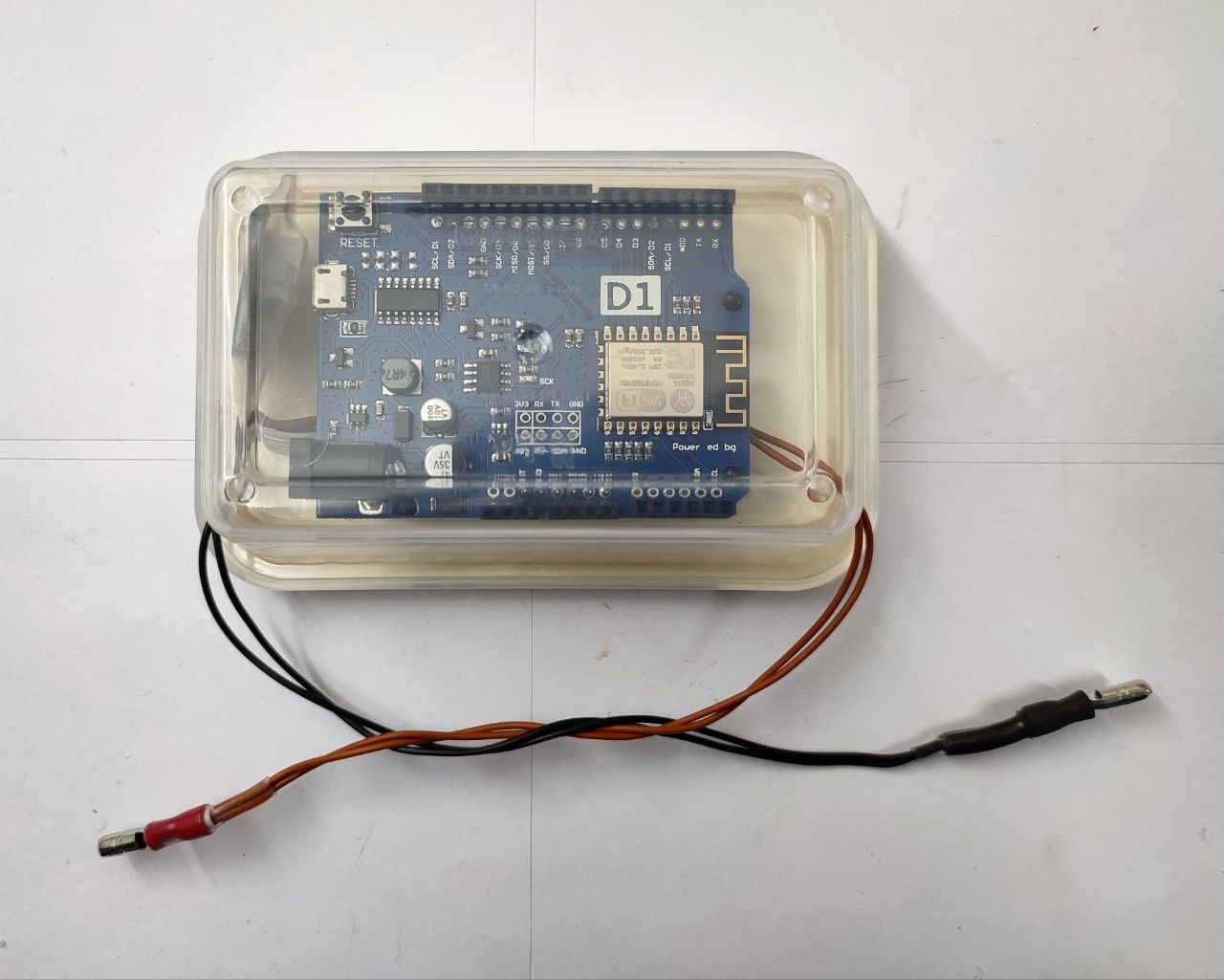
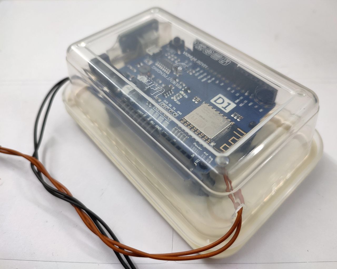
I’m not using any strain relief in this version, and the exit holes are intentionally oversized to allow for some ventilation, if it’s needed.

Four completed monitors, one for each battery. As an aside, I looked at Stuart Pittaway’s diyBMS and it uses a single ESP8266 module because his design relies on an isolated I2C bus that adds complexity and necessitates a custom PCB. The cost of each battery monitor here is around Rs 500, which is fairly reasonable despite using hobbyist modules.
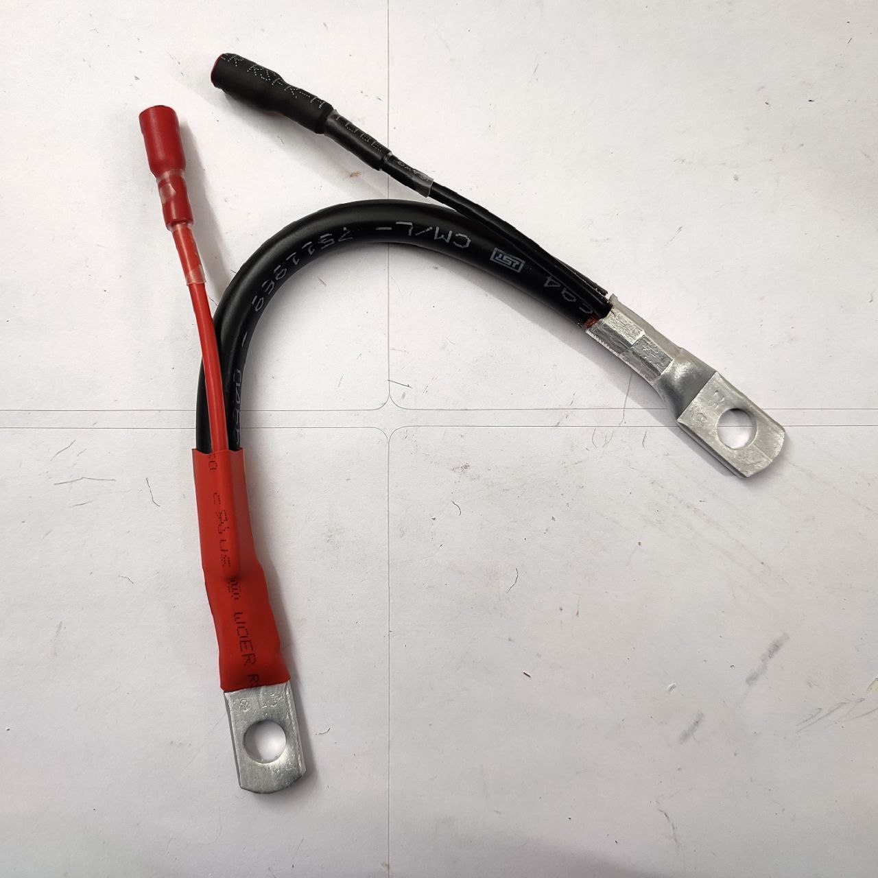
These are short battery connecting wires that I made with a separate wire to connect to each battery monitor. I would have liked shorter wires, but heatshrinking them would’ve been difficult. These aren’t necessary, you can use your existing battery wires and just crimp a ring terminal for the battery monitors, like the two smaller ones here:
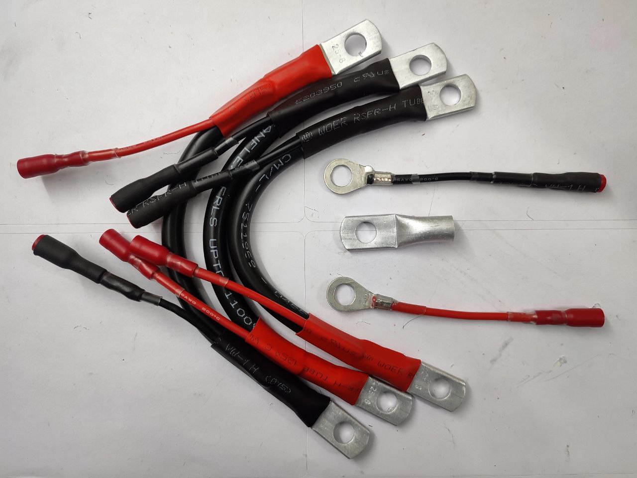
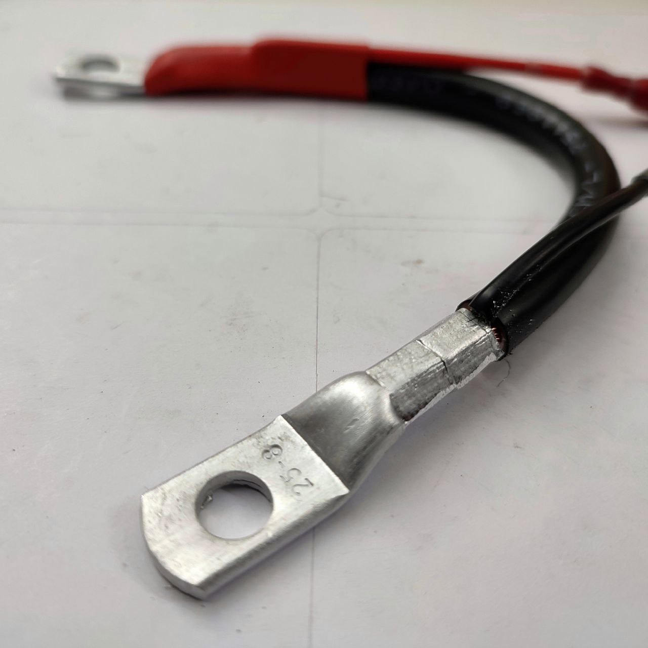
Before heatshrinking these larger aluminum ring terminals (they take 25 sq mm wire and have a 8mm hole), it’s a good idea to sand down the edges of the crimp since they could tear the heatshrink.

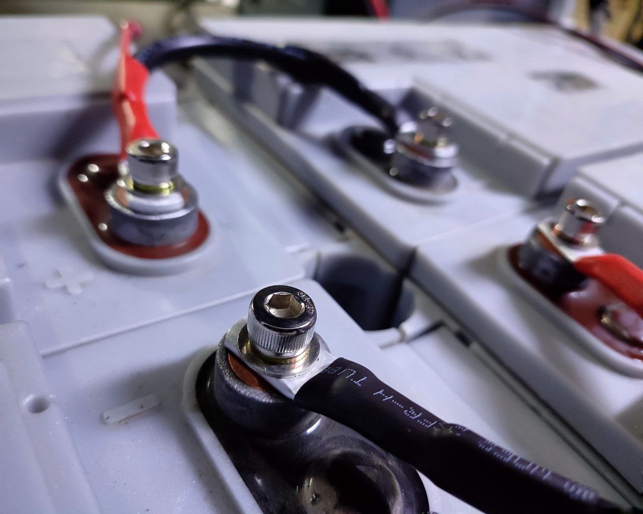
On the left, the bolts that came with the inverter, the middle is a high quality stainless steel hex head bolt and on the right is an absolutely beautiful socket head bolt. These are all M8 and the socket head one is 25mm long, purchased along with the flat washer and spring washer from indialocalshop:
https://indialocalshop.com/fasteners/sockets/ssallenm8.html
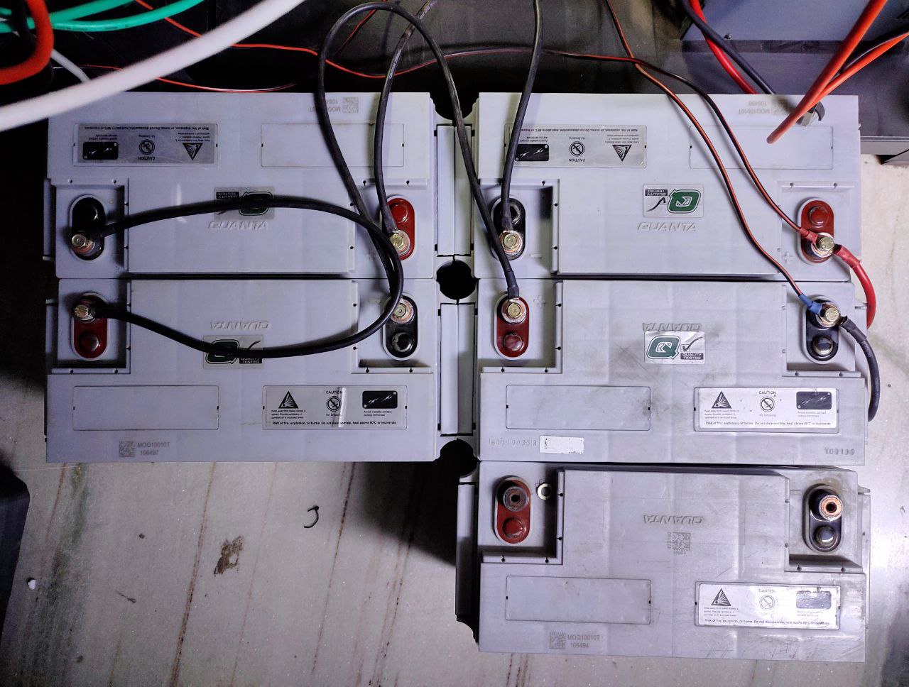
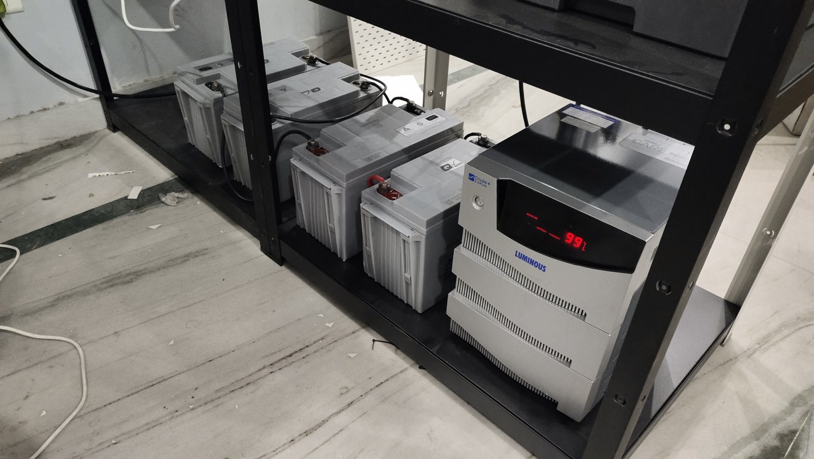
Here, the batteries are connected with the long 16 sq mm wires that came with the inverter (the fifth battery is the dead one that’s been replaced)
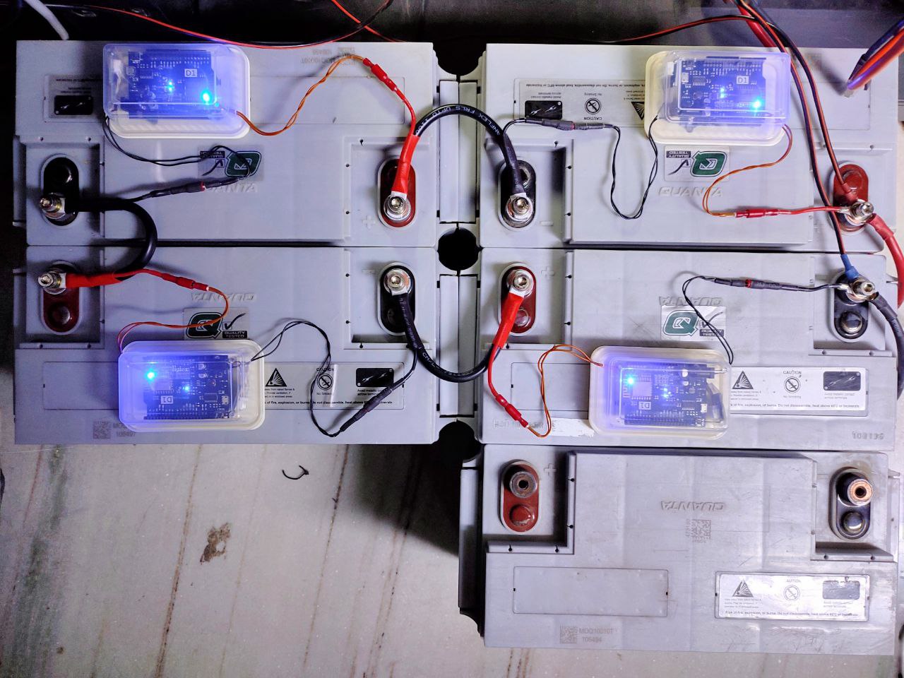
With the shorter cables and the battery monitors installed.
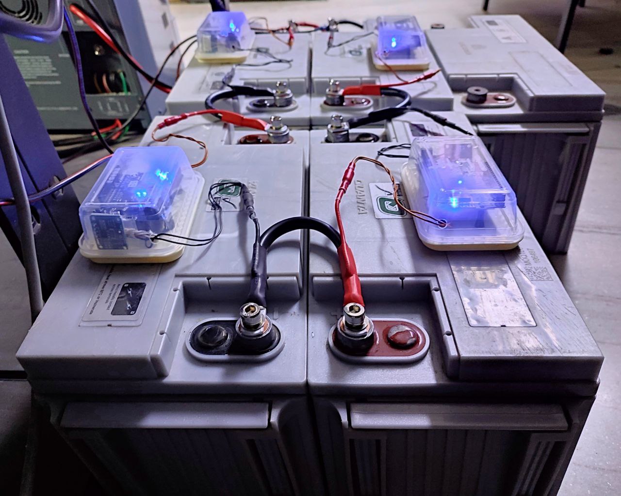
Not too bad for what is essentially a prototype, maybe shorter wires next time.
These socket head screws are so pretty.
[HR][/HR]
[HR][/HR]
[HR][/HR]
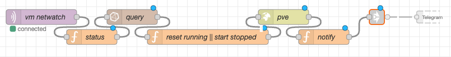
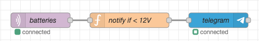
From here, it’s configuring Tasmota with your integration of choice (mine was Mikrotik’s RouterOS and Telegram, but I’ll be moving it over to MQTT/Node Red/InfluxDB/Grafana.