I’m going to consolidate my experiments and adventures with inverter batteries here.
Previous posts on the topic:
One of the earlier warning signs I noticed (and chose to ignore) when I first started trying to understand why my inverter batteries died so quickly (2.5 years) was this:
From: [
https://www.amaronbatteryinverterchennai.com/files/amaron/Quanta
Silver Book.pdf](’
https://www.amaronbatteryinverterchennai.com/files/amaron/Quanta%20Silver%20Book.pdf’
)
And from:
https://amaronquanta.com/wp-content/uploads/2022/04/Amaron_OM_Manual.pdf
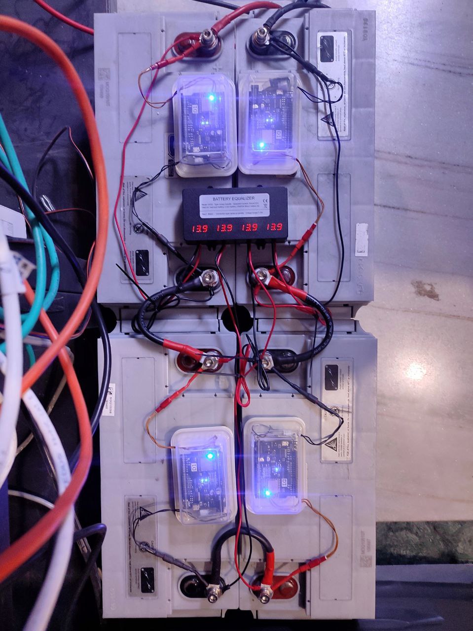
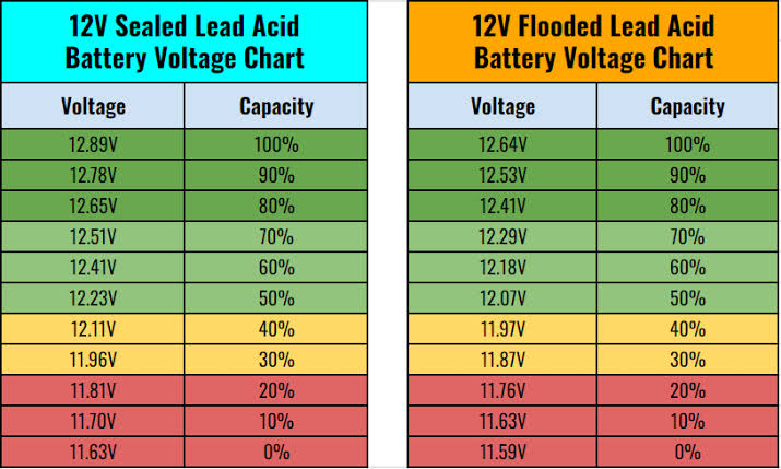
The inverter I’m using (Luminous Cruze+) floats the batteries at around 13.9V per battery, which sounds like it’s a lot higher than what’s recommended and may have been a reason why my batteries died so quickly.
The charging/float voltage on this inverter is not configurable and short of reverse engineering/modifying the controller board, I’m not left with any option other than to exchange my sealed batteries for flooded ones.
But I really like these batteries, so I spent several weeks searching the internet and found this somewhat relevant post/reply from twenty (!) years ago:
https://maker.pro/forums/threads/apc-smart-ups-battery-float-voltage-adjustment.44477/
(To answer their original question, the calibration procedure is now well documented elsewhere and here:
)
It really sounds like they had a very similar problem to mine back then — high float voltage shortening the life of SMF batteries.
A reply stood out:
This made sense to me, the idea/practice of lowering the float voltage with a diode. So my searchings were renewed for a high power diode and I found these 40A and 70A rated diodes at mathaelectronics.com:
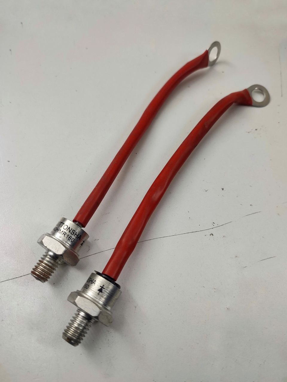
I got a few them and started thinking about how I’d want them wired up. I’d need them to be able to conduct electricity in both directions, so that the inverter can both drain and charge the batteries. And I’d want at least a 1.5V drop during float charge, so as to bring the +55V float voltage down to 54V. A single diode drops voltage by about 0.7V. I came up with this arrangement:
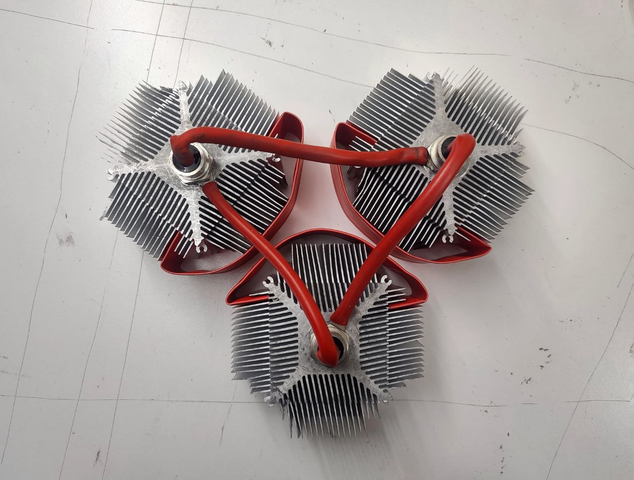
It looks pretty awesome haha, it’s basically three diodes arranged in a circle. The idea is that the battery is connected to one diode on the top left, and the inverter to the diode on the top right. So electricity flows through one diode when the inverter is pulling power from the battery, and it flows through two diodes when it’s time to charge the batteries.
The heatsinks are old LGA775 ones with a center hold drilled and tapped for M8. I added a some heatshrinking to serve as insulation between the heatsinks. I’m expecting about 30W of heat dissipation at 1000W (1000W/48V is 20A, maximum voltage drop of this diode according to it’s datasheet is 1.4V and 1.4V x 20A is 28W).
Here’s it installed:

I checked the voltages, and the float voltage did drop down to 54.2V which was excellent. Then I did a load test and it exploded:
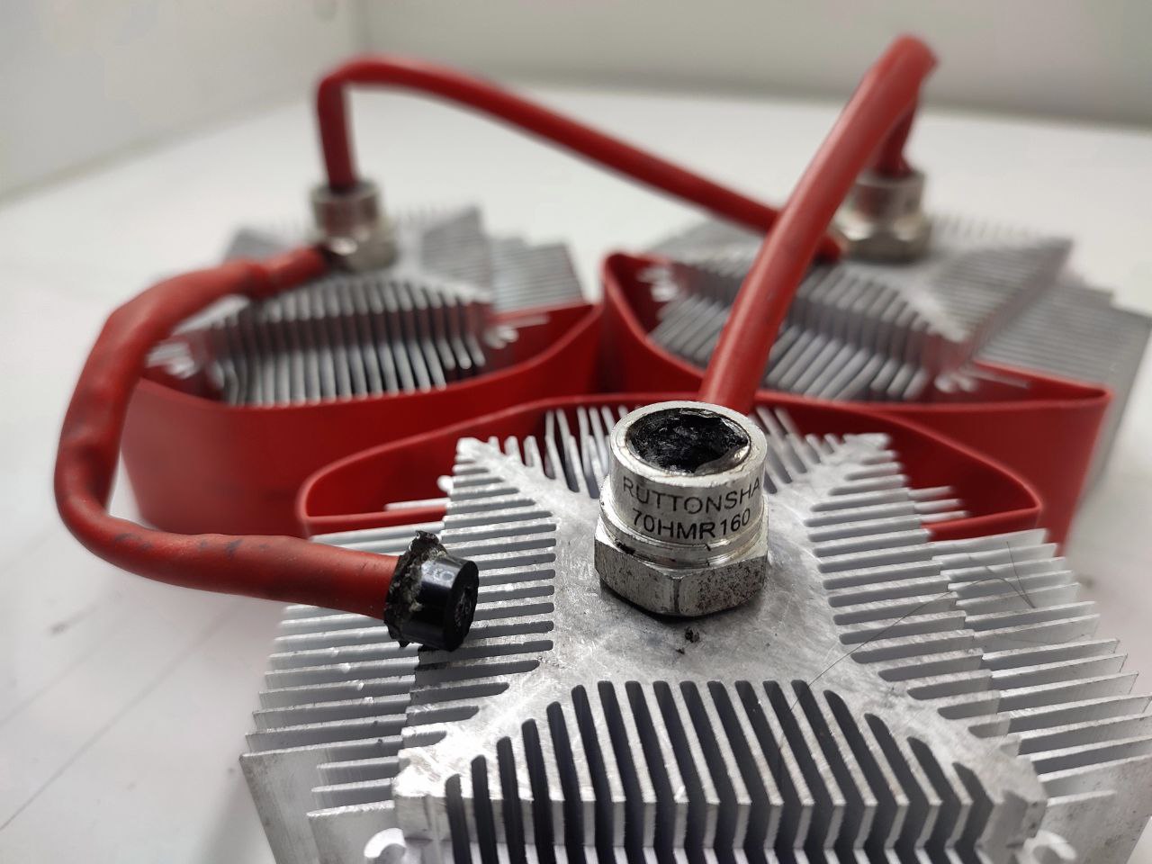
It’s rated for 70A, but that’s probably for AC. Most people de-rate AC ratings by a factor of 10 for DC, so this was unavoidable. I tried the other diodes I got, thinking this may have been a defective diode but no, they all overheated and failed.
Now, I could bring my enthusiasm for a solution into question and either continue my search to find better diodes and come up with some kind of elaborate solution using a solid state relay or dc switching contactor which would bypass the diode when there’s a power cut (thereby preventing the overheating explosions) or —* I could even build an external charger for the batteries using Ashapower’s Solar MPPT chargers that have configurable charge settings, you could theoretically run them off DC power supplies instead of solar panels but that would probably cost just as much as *— going about replacing my inverter with something that’s compatible with SMF batteries (charging at 13.5V per battery).
Whichever way I go, I’ll update here whenever I go that way, haha.