Device to measure power consumption for 220v devices!
There seems to be a lot of interest in tech enclave for measuring the amount of power that is drawn by the various devices in the house. So Im reproducing a blog that I had written last year on how to make your own "kill-a-watt" device. Im still using the device that I had and it is a great help.
Here is the original blog :
Random musings...: "Kill A Watt" for 220v !
And the contents reproduced below for those who cannot access blogs from work :
I have been thinking a lot about how to conserve power. Part of this is driven by the ever increasing number of gadgets in the house which are leading to larger and larger electricity bills !
I did a lot on searching on the net to figure out if a device to measure the amount of current being drawn by any device is available on the net. Sure it was, "Kill a watt" is a much used, much loved device to do this exactly. Unfortunately, like most things American, it uses 120v and there is nothing for the 220v side of the world. And one 220v option available for Europe was just ridiculously expensive.
So that set me thinking that this should not be too difficult to build. With the help of a few friends who were good at circuits, I finally built it for just Rs 750 ($15).
View attachment 11427
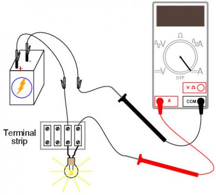
Here is the circuit diagram of the same. Remember that the current has to flow in series through the multimeter. The current has to pass through the multimeter and the selected component in series to measure the current flowing through the circuit.
Now for some live photos and DIY steps of how I to made it.
Disclaimer : Remember that we are talking of live current here, so the standard disclaimers apply. If you electrocute yourself or burn down your house, it is all your fault !!! Be careful with the circuits and do not connect anything till you are reasonably confident it is all going to work.
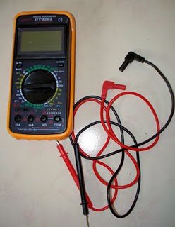
What do you need ? A digital multimeter that can measure current, these are available for Rs 600 in any good electrical shop. Remember that the multimeter's available for Rs 200 cannot measure current. They only work on DC and measure current voltages. (If there is a doubt, check if there is a "A~" option among the options).
This is the one I used:
View attachment 11423
You also need a ready made switch box, again available in any electrical shop for Rs 50. Make sure you get a 5amps model as I would not be comfortable connecting a 15amps component to the multimeter.
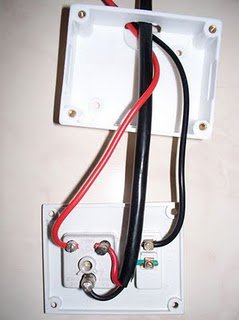
Now, you are ready to connect the multimeter to the switch box. Chop off one end of the multimeter cable so that you can connect it directly to the switch box. Remember to cut the cable from the side which does not connect to the mutimeter (It will be a special molex cable on one end to connect to the multimeter and a sharp pin on the other side. Cut the side with the sharp pins). Current flows from the mains to the box and the multimeter wires are connected in series.
Here is the snap of the same.
View attachment 11425
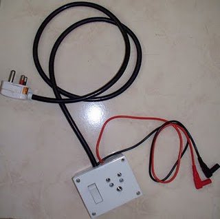
Close the box and bring the cables from one side of the box so that no live wires are hanging out. This is how the completed box looks like:
View attachment 11424
Now connect the multimeter molex cables to the multimeter and leave it there. This is because current will be flowing through the molex ends and you do not want them to touch the ground.
That is it basically. Set the multimeter to the 20amps mode to make sure the fuse does not blow, connect ANY device to the box and plug the box to the mains. Switch on the current and the device and you can start seeing live data on how many amps are being drawn by the device. If you multiply the amps reading with 235, you get the number of watts being drawn by the device. Note that even though India claims to run on 220v, we actually get anywhere between 220v and 240v in the mains. I seem to be getting 235v almost constantly, hence I multiply by 235. You can measure the voltage in your house using the same multimeter at the precise moment you are taking the reading if you want perfect figures, otherwise 235 is a close approximation.
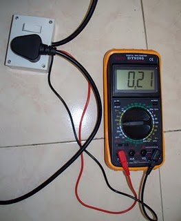
See the picture here of my old 17" TFT monitor monitor connected to the circuit.
View attachment 11426
The 17" TFT monitor is drawing 0.21 amps, which translates to 50 watts of current being used. Note that my new 22" LCD draws a similar amount of current which shows how electronic components are getting more and more power efficient !!!
That is it folks, connect any 5amps device to the circuit and measure the current being used. Not precise, but a pretty close approximation of power usage.
A homemade DIY "Kill a watt" for 220v at a cost of Rs 750 !!!
There seems to be a lot of interest in tech enclave for measuring the amount of power that is drawn by the various devices in the house. So Im reproducing a blog that I had written last year on how to make your own "kill-a-watt" device. Im still using the device that I had and it is a great help.
Here is the original blog :
Random musings...: "Kill A Watt" for 220v !
And the contents reproduced below for those who cannot access blogs from work :
I have been thinking a lot about how to conserve power. Part of this is driven by the ever increasing number of gadgets in the house which are leading to larger and larger electricity bills !
I did a lot on searching on the net to figure out if a device to measure the amount of current being drawn by any device is available on the net. Sure it was, "Kill a watt" is a much used, much loved device to do this exactly. Unfortunately, like most things American, it uses 120v and there is nothing for the 220v side of the world. And one 220v option available for Europe was just ridiculously expensive.
So that set me thinking that this should not be too difficult to build. With the help of a few friends who were good at circuits, I finally built it for just Rs 750 ($15).
View attachment 11427
Here is the circuit diagram of the same. Remember that the current has to flow in series through the multimeter. The current has to pass through the multimeter and the selected component in series to measure the current flowing through the circuit.
Now for some live photos and DIY steps of how I to made it.
Disclaimer : Remember that we are talking of live current here, so the standard disclaimers apply. If you electrocute yourself or burn down your house, it is all your fault !!! Be careful with the circuits and do not connect anything till you are reasonably confident it is all going to work.
What do you need ? A digital multimeter that can measure current, these are available for Rs 600 in any good electrical shop. Remember that the multimeter's available for Rs 200 cannot measure current. They only work on DC and measure current voltages. (If there is a doubt, check if there is a "A~" option among the options).
This is the one I used:
View attachment 11423
You also need a ready made switch box, again available in any electrical shop for Rs 50. Make sure you get a 5amps model as I would not be comfortable connecting a 15amps component to the multimeter.
Now, you are ready to connect the multimeter to the switch box. Chop off one end of the multimeter cable so that you can connect it directly to the switch box. Remember to cut the cable from the side which does not connect to the mutimeter (It will be a special molex cable on one end to connect to the multimeter and a sharp pin on the other side. Cut the side with the sharp pins). Current flows from the mains to the box and the multimeter wires are connected in series.
Here is the snap of the same.
View attachment 11425
Close the box and bring the cables from one side of the box so that no live wires are hanging out. This is how the completed box looks like:
View attachment 11424
Now connect the multimeter molex cables to the multimeter and leave it there. This is because current will be flowing through the molex ends and you do not want them to touch the ground.
That is it basically. Set the multimeter to the 20amps mode to make sure the fuse does not blow, connect ANY device to the box and plug the box to the mains. Switch on the current and the device and you can start seeing live data on how many amps are being drawn by the device. If you multiply the amps reading with 235, you get the number of watts being drawn by the device. Note that even though India claims to run on 220v, we actually get anywhere between 220v and 240v in the mains. I seem to be getting 235v almost constantly, hence I multiply by 235. You can measure the voltage in your house using the same multimeter at the precise moment you are taking the reading if you want perfect figures, otherwise 235 is a close approximation.
See the picture here of my old 17" TFT monitor monitor connected to the circuit.
View attachment 11426
The 17" TFT monitor is drawing 0.21 amps, which translates to 50 watts of current being used. Note that my new 22" LCD draws a similar amount of current which shows how electronic components are getting more and more power efficient !!!
That is it folks, connect any 5amps device to the circuit and measure the current being used. Not precise, but a pretty close approximation of power usage.
A homemade DIY "Kill a watt" for 220v at a cost of Rs 750 !!!