Teardown & Rebuild of a MuscleGrid LiFePO4 Server Rack Battery

We had two extended power outages today, apart from the full discharge I did earlier, and I got a chance to test the round-trip efficiency (discharge/charge * 100) of LiFePO4 first hand!

The battery provided 7.206kWh of energy and required 7.424kWH to charge back up to full, that’s 97%! At 83% SoH!

THIS IS THE FUTURE.

The absolute best case scenario I got with those expensive Amaron Quanta VRLA/AGM batteries was 85% when they were brand new, even that number is a generous estimation.

Of course, I’ll need to find out how efficient the charger in the Luminous Cruze inverter is and then we’ll have a much more accurate number for real-world scenarios, this 97% is purely academic at this point.

Speaking of the Luminous Cruze, it can detect the high voltage cutoff by the BMS and switch from Absorption to Float charging, which means it drops from 14.6x4 to 13.9x4 automatically. Witnessing that gave me chills, it was so cool.

Charging mode explainer:

Lead Acid batteries are first charged up in constant current mode, also known as Bulk Mode. The battery is charged at the maximum amps the charger is configured to deliver, this goes up to about 80% of the battery’s capacity.

When the charger detects a certain voltage threshold is reached, it switches to Absorption/Boost mode, this is constant voltage mode, so that the remaining 20% is topped up at a lower current.

Once the the current drops off then it switches to Float Mode, where the voltage is dropped slightly to keep the battery from self discharging.

The Luminous Cruze switched to Float Mode because it no longer detected the battery’s voltage, it detected its own charging voltage in Absorption mode, and assumed the battery was now at that voltage, initiating the switch to Float Mode (thereby preventing over-charging)

Now the only thing I wish was different was the charging amps, the inverter did not cross 10A, which is far too low. I guess it’s charging at the C20 rate since I configured the inverter to think it had a 200Ah battery attached.

So sometime in the near future, I’m going to have to build a separate charger, probably a 1000W one, just so that I can get the battery charged up quicker, I don’t want to wait 5 to 10 hours to get back to full capacity even if its pragmatic.

@rsaeon where you got dc cables that is connecting batteries and bms.

ordered jk 100A 8s bms. it does not come with the cable.

what is the size of wire I have take for 100A (but battery rated is 50A 24v continuous)?

If you want ready-made cables, there’s Daystar: https://www.daystarsolutions.in/ They’re also on Amazon.

I would say that 35 sq mm is a good size for 100A, but it can handle twice that much for shorter lengths.

For 50A, most inverters come with 16 sq mm cables so 35 is two sizes up, a generous safety margin.

1 Like

Names are easily the hardest part of programming for me, here’s what I’ve come up with for this battery pack:

RM01LFP16S100A


RM is rack-mount, other batteries maybe FS for free-standing or IN for internal or even WM for wall-mount

01 is battery number, I don’t expect to have more the 99 batteries in this life

LFP is battery technology, I might explore LTO in the future.

16S is cell count

100A is nominal amp-hours

This whole string is presented as a level in tasmota’s MQTT topic:

ee/battery/tele/RM01LFP16S100A/meter

I can use then use this data programmatically to record bms information for logging and stats display.

The meter level indicates data from my own shunt, this contains voltage of the battery, current/power in/out of the battery and since the shunt cannot differentiate between current flow directions, we have a CT sensor to indicate if we have mains power available (if it’s available, then battery is charging, otherwise it’s discharging).

There are other ways to detect if mains power is available, like with a mains-rated optocoupler or mains-rated relay but I wanted something as non-invasive as possible, and a split-clamp CT sensor was perfect.

If a completely independent data source was required to detect mains AC then a separate esp8266 module powered by a usb adapter would work and it would be a little cheaper than the CT sensor (esp01 + usb programmer + 5W adapter). It’ll work as a digital canary.

Sometime in the future, there’ll be two other data-reporters, one for BMS data through the BMS communication interface and one for my own individual cell voltage monitors. I want to standardize on using my own tasmota-based voltage monitors since it’s unclear how accurate any future BMS would be.

After this project, I have a few more. A 72V pack for an online UPS, a 48V pack for another online UPS, a 24V pack for a line-interactive UPS, a 12V one for a home inverter and a 9.6V one with leftover cells from this project for a DIY DC UPS:

1 Like

This is my favourite method to detect if mains is available or not. Cheap and reliable. Works on both 5v and 3.3v.

Not tested yet but 99% sure it is solid.

3 Likes

Here’s version 2 of the data-logging function node in nodered. It receives data from tasmota through mqtt and processes it in one of two ways.

If somehow the pzem’s total kwh reading resets or is lower than the last recorded reading, then it pushes out an update back to the tasmota device, setting the correct total kwh reading.

Otherwise, it sends off data to an influxdb out node for logging.

So this function node has two outputs.

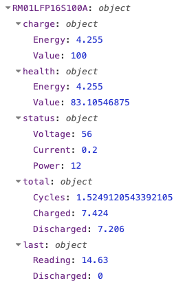
// msg.topic = ee/battery/tele/RM01LFP16S100A/meter/SENSOR
// 10-second update interval
// Current always positive
// idle current is 1A

if (!msg.payload?.ENERGY || !msg.payload?.ANALOG?.CTEnergy) return [null, null];

const battery_id = msg.topic?.split('/')?.[3];
if (!battery_id) return [null, null];

const [cellCount, ampHours] = battery_id.match(/\d+/g)?.map(Number).slice(1) ?? [];
if (!cellCount || !ampHours) return [null, null];

const measurements = flow.get(battery_id) || {
    bat_voltage: 0,
    bat_current: 0,
    bat_power_w: 0,

    cycle_count: 0,
    cha_nrg_kwh: 0,
    dch_nrg_kwh: 0,

    soc_percent: 0,
    soc_nrg_kwh: 0,

    soh_percent: 0,
    soh_nrg_kwh: 0,

    tot_nrg_kwh: 0,
    dod_nrg_kwh: 0
};

const designCapacity = 3.2 * cellCount * ampHours / 1000;
const actualCapacity = measurements.soh_nrg_kwh || designCapacity;

const { Voltage, Current, Power, Total } = msg.payload.ENERGY;

if (Total < measurements.tot_nrg_kwh) {
    msg.payload = `EnergyToday 0; EnergyTotal ${measurements.tot_nrg_kwh * 1000}`
    msg.topic = msg.topic.replace('SENSOR', 'Backlog')
    msg.topic = msg.topic.replace('tele', 'cmnd')
    return [null, msg];
}

measurements.bat_voltage = Voltage;
measurements.bat_current = Current;
measurements.bat_power_w = Power;

const fullCharge = Voltage > 3.45 * cellCount;
const lowBattery = Voltage < 3 * cellCount;

const gridSupply = msg.payload.ANALOG.CTEnergy.Current > 1;

const delta = Current < 1 ? 0 : Total - measurements.tot_nrg_kwh;
measurements.tot_nrg_kwh = Total;

if (gridSupply) {
    measurements.soc_nrg_kwh += delta;
    measurements.cha_nrg_kwh += delta;
    measurements.dod_nrg_kwh = 0;
} else {
    measurements.cycle_count += delta / actualCapacity;
    measurements.soc_nrg_kwh -= delta;
    measurements.dch_nrg_kwh += delta;
    measurements.dod_nrg_kwh += delta;
}

measurements.soc_percent = measurements.soc_nrg_kwh / actualCapacity * 100;

if (gridSupply && fullCharge && delta === 0) {
    measurements.soc_nrg_kwh = actualCapacity;
    measurements.soc_percent = 100;
}

if (!gridSupply && lowBattery) {
    measurements.soh_percent = measurements.dod_nrg_kwh / designCapacity * 100;
    measurements.soh_nrg_kwh = measurements.dod_nrg_kwh;
    measurements.soc_percent = 0;
    measurements.soc_nrg_kwh = 0;
}

measurements.soc_nrg_kwh = Math.min(Math.max(measurements.soc_nrg_kwh, 0), actualCapacity);
measurements.soc_percent = Math.min(Math.max(measurements.soc_percent, 0), 100);

flow.set(battery_id, measurements);

const mount_type = battery_id.substring(0, 2);
const chemistry = battery_id.substring(4, 7);

msg.payload = [
    measurements,
    {
        battery_id,
        mount_type,
        chemistry
    }
]

return [msg, null]

Some notes/comments:

The measurements object contains a preliminary set of values, it took a while to come up 12 different variable names that were exactly 11 characters long haha.

I added units in the variable names for power and energy, I imagine I might use them in graphs somewhere. I learned that NRG is a clever way to say energy.

For now, we’re assuming we’re using LFP chemistry so calculations are based on that, this will need to be changed or put into a variable at some point in the future.

I changed the name of mainsAC to gridSupply as that made more sense for a boolean value.

The datasheet for the cells that I’m using specify that charging should be cut when the current drops to 5A, this is called tail current. But since my inverter was designed for lead acid batteries, it eventually switches to float charging and keeps putting out power to the batteries (1w to 2w) which skews the round-trip efficiency values (cha_nrg_kwh and dch_nrg_kwh) over the course of a few days.

I’m calling this insignificant current as “idle current” and put it at 1A for now. Any charge/discharge below 1A won’t be counted.

A non-zero value for dod_nrg_kwh indicates a power outage in effect, I thought that was unexpectedly useful.

The rest of the code is self-explanatory. You could run it through ChatGPT and get a comprehensive explanation if you like.

For the moment the data is dumped every 10 seconds into a bucket in influxdb that has a ttl of 30 days. Maybe I’ll change that to 60 seconds, if the bucket gets too big with multiple batteries. Later, I’m going to have to do an hourly average/max aggregate of this data into another bucket for long term storage.

I’m also going to have to do something about unintended restarts of this nodered instance, it should pull data from influxdb whenever that happens.

1 Like