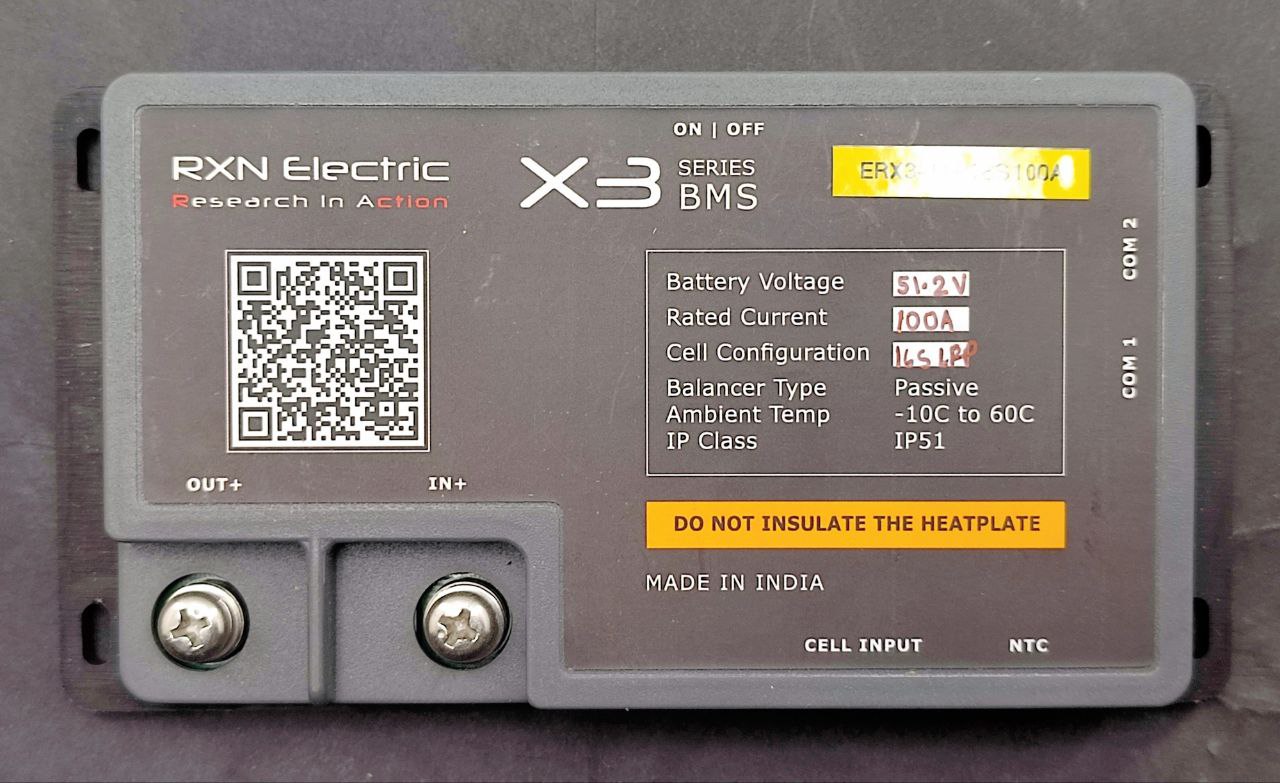
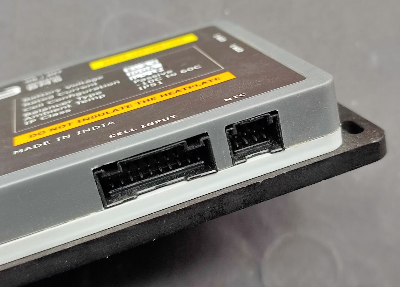
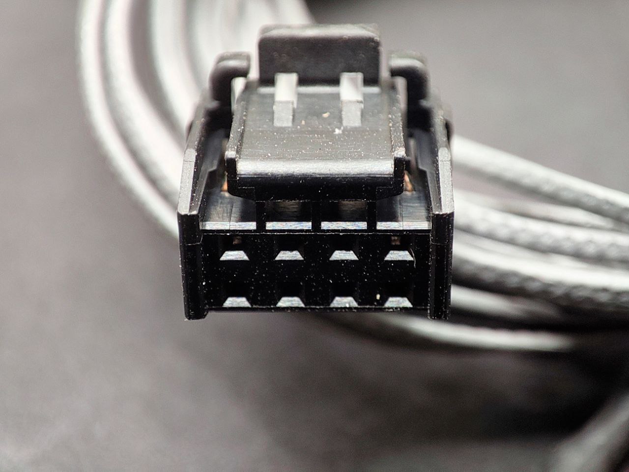
So thats a 20 cell connector/ port but only 16 is used. Any documentation.
How much current can it dispate per cell during balancing, since this is a passive balancer it will bleed it off by heat.
I will also in the not too distant future will add LFP, so will be keeping a eye on your progress.
For people using regular inverters which use lead acid battery where it will trickle charge after reaching the set voltage. Usually about 100ma to 200ma depending on the size of the battery. So in those conditions a LFP battery connected with a BMS it will the bleed those excess energy as heat. Wondering how this will dispate the heat with no fans. In my inverter when it trickle/float charges the current is below what my shunt can register and in a clamp meter its within the margin of error.
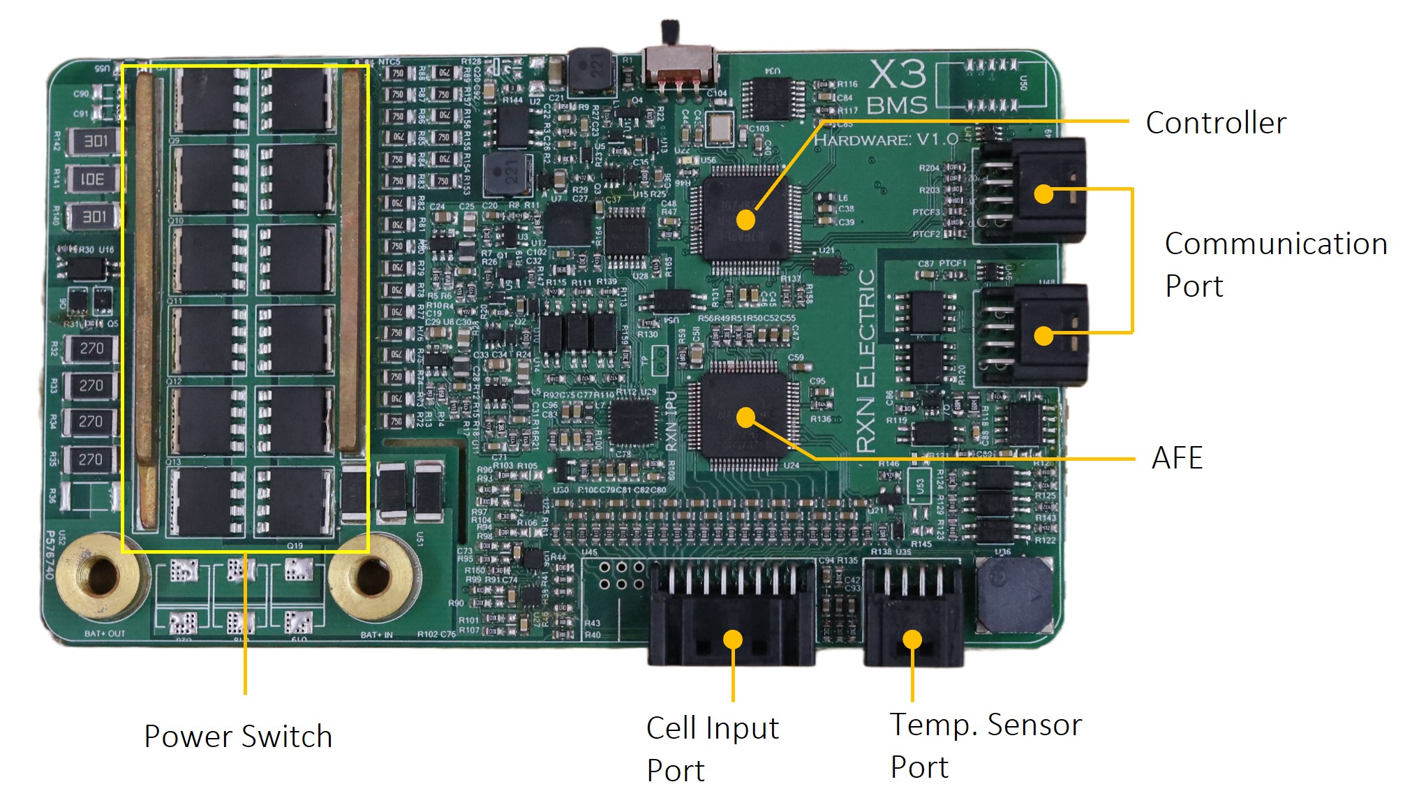
They have models upto 24S, I’m guessing they’re reusing the basic design, with pricing reflecting the quality of their analogue front-end (1mV accuracy in the X3 series and 5mV for the X1 series) and the number of mosfets, depending on how much current it’s rated for:
The PCB also shows the unused pins for the balance leads for that model, there’s 24 pins in total.
I figure this is the case since all of the X3 100A models are priced the same (Rs 10k) and the cheapest X1 30A model is priced pretty high at Rs 4K, probably because it uses the same design.
It’s a really well-designed product, they just needed to make one PCB and they have over 50 SKUs based on it: LFP, NMC, 30A to 100A, 4S to 24S. Can you tell I’m a fan? haha
The balance current is just 50mA, but interestingly they say their microcontroller does coulombic balancing — I’m excited to see that since I’m mixing two different types of cells in the same battery pack.
I’m guessing they depend on passive dissipation, there’s warning text on the device saying it should not be covered and they have some models with a heatsink.
I cannot state this enough, but this is one of rare products that I’m really proud to see come out of India, right up there with Ashapower. Both of these companies do not design to meet a price target, only to meet an engineering goal.
I’ve lost count how many times I revisit your older posts about your setup. It’s really well done and a source of inspiration.
At 1C this battery should be able to provide 5000W easily, but my inverter is ~3000W.
I might get another inverter and connect it to the same battery or I might not.
I’m thinking maybe I should build this battery to handle 100A? I guess the safety factor itself should be worth it (so that nothing overheats or melts or catches fire because of undersized connections).
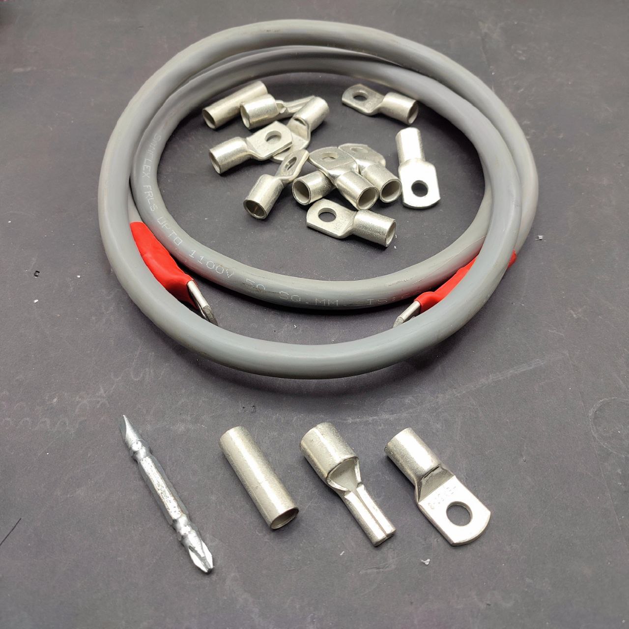
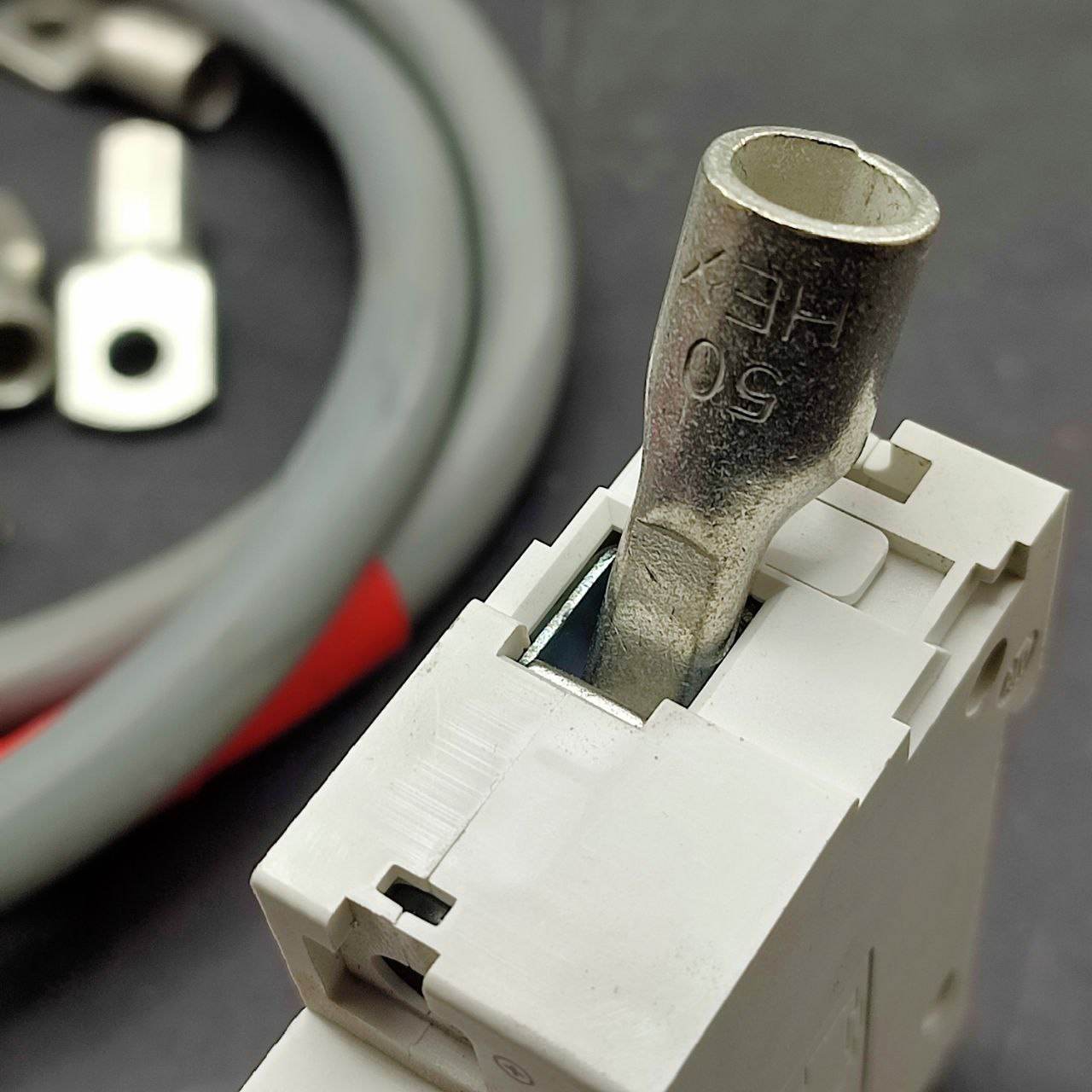
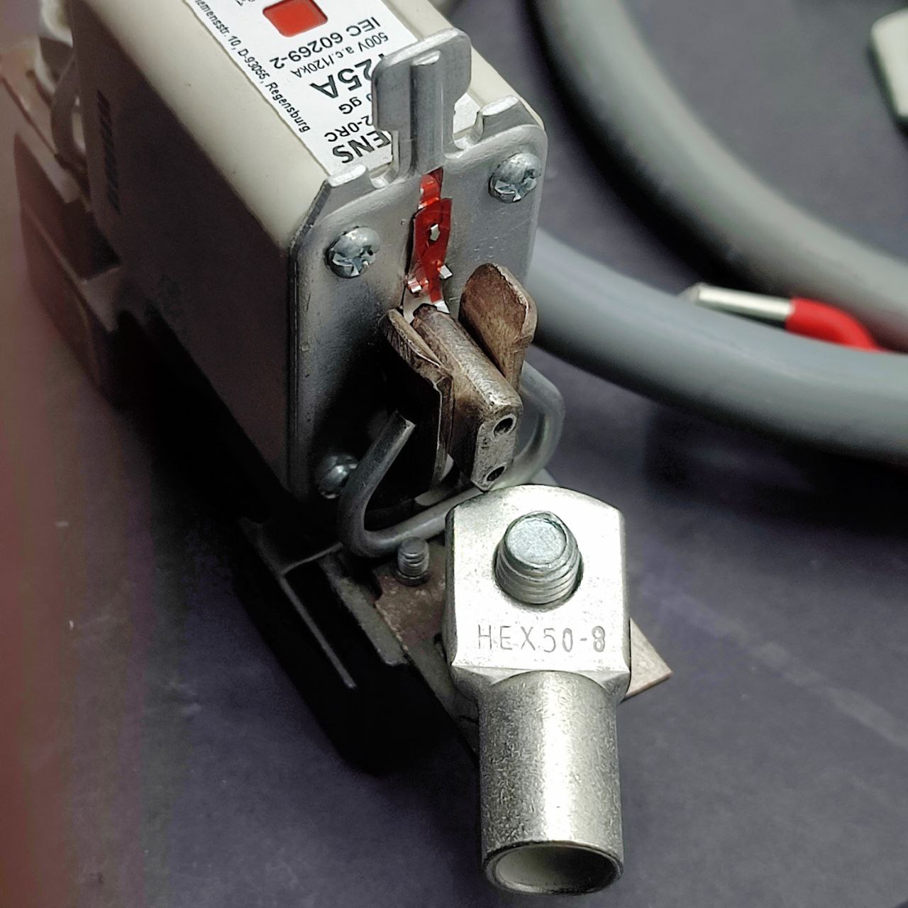
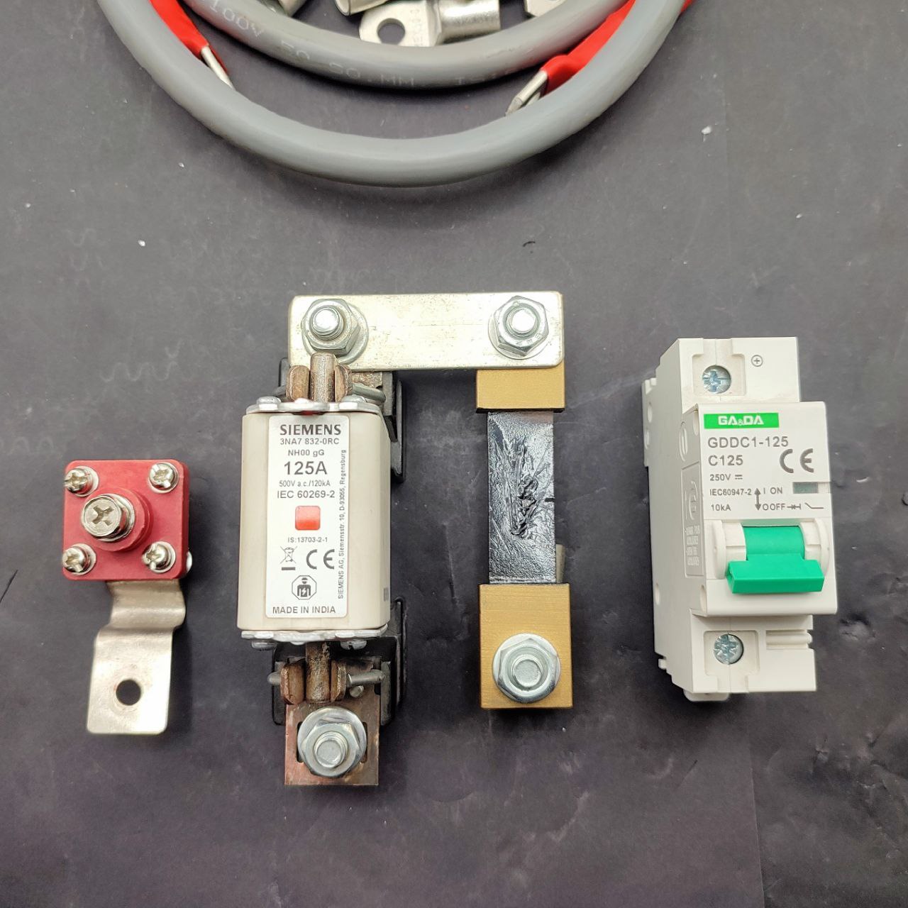
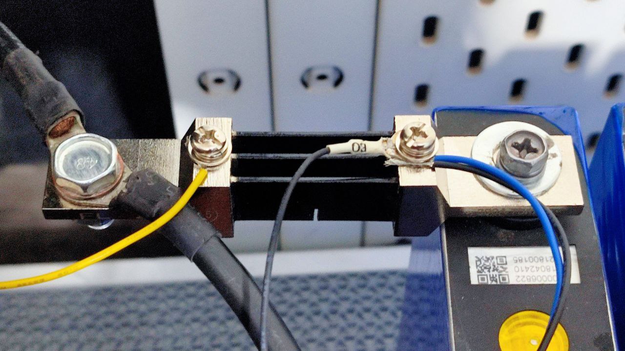
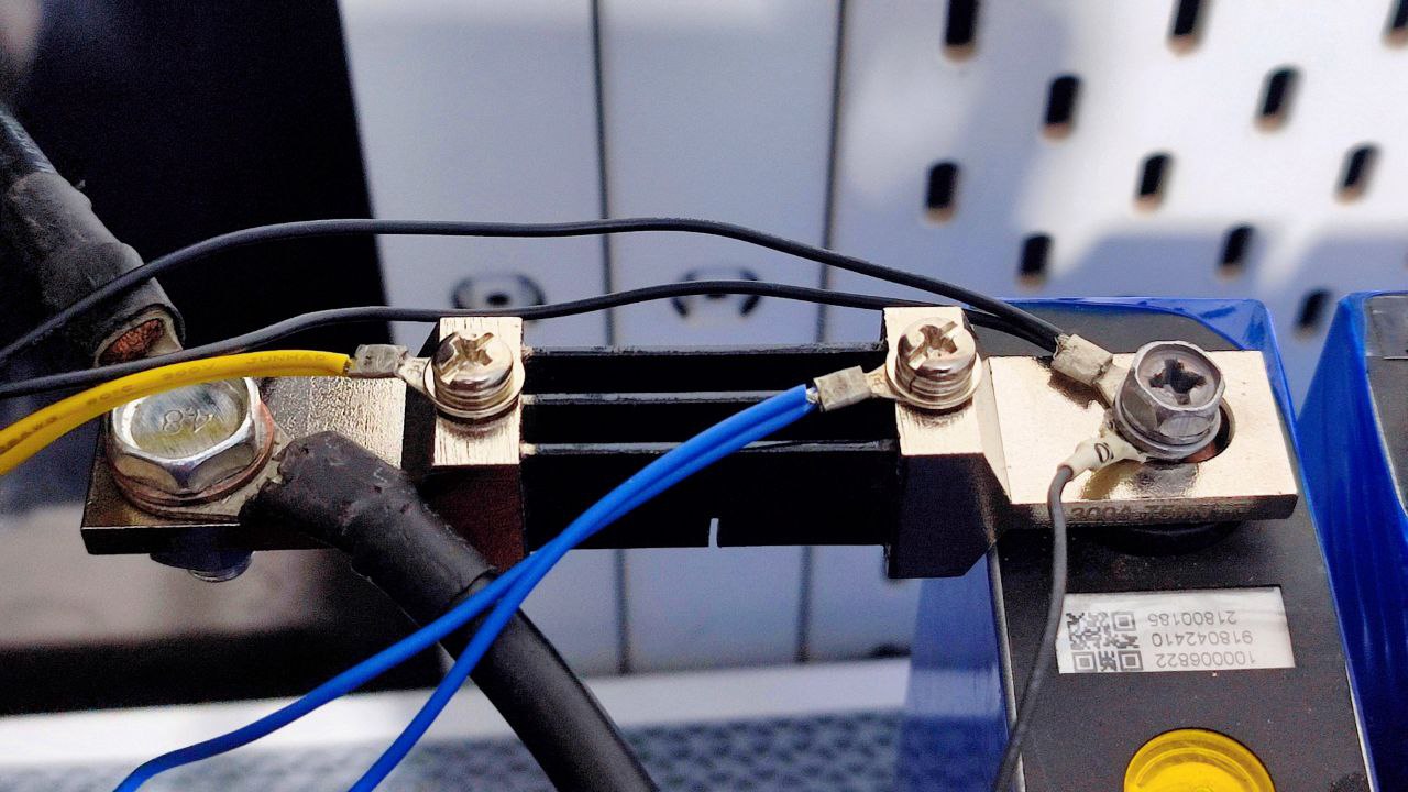
So far I’ve got a 100A terminal, a 125A NH type fuse, a 100A current shunt and a 125A isolator:
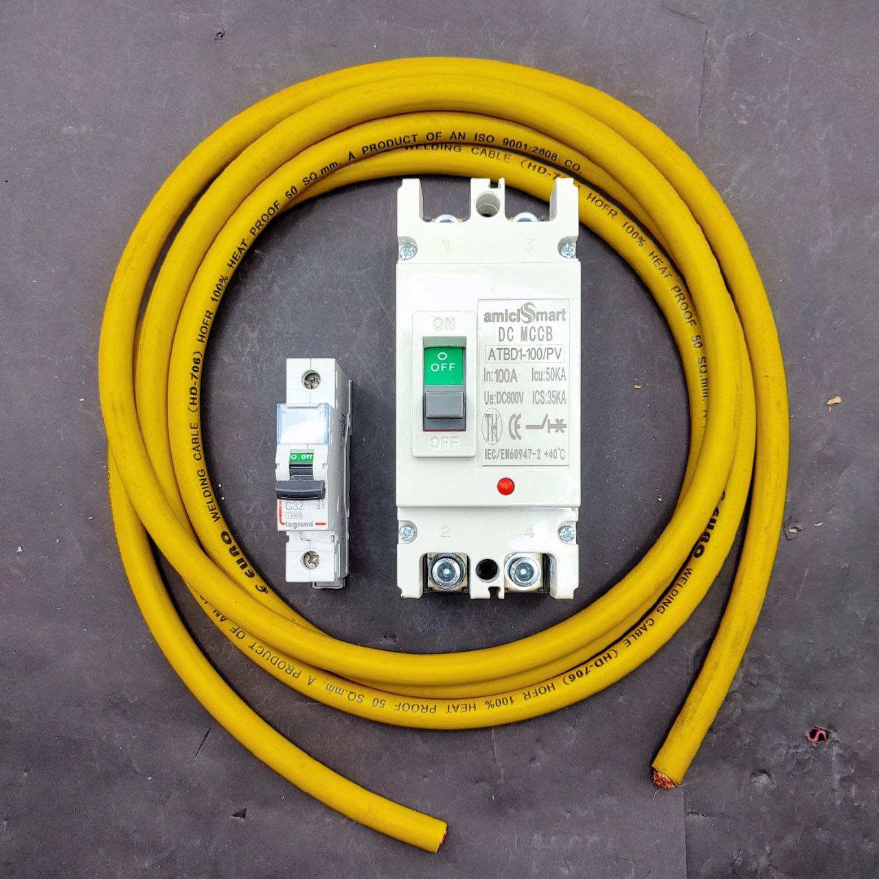
I’ll also have a circuit breaker that’ll arrive next week.
Would having both isolator and circuit breaker be redundant? The circuit breaker is for external loads (inverter), the isolator is for internal loads (monitoring) if I ever need to replace the fuse.
I’m a little confused, maybe the isolator is unnecessary.
I think I want the isolator before the BMS, would that make sense? It wouldn’t be wasted there.
The current shunt sizing is another topic but later.
If you want to switch on or off the load be it to the inverter input or output, AC or DC. You need to use a Circuit breaker. You can use a isolator, only when there is zero current flowing, else expect arcing. The Arc in a DC voltage is even bigger.
You wont need a isolator for the BMS since the balance leads are already connected, so no arcing. Its like the the pre charge relay in EV before the main contactor turns On.
Bus bar are fine just to be safe I would probably put some heat shrink on Non contact area of bus bar. Never know a simple screw driver or spanner may end up touching the other terminal no matter how far it is.
Would’ve been nice if the Amici people took pride in their work and designed the laser etch graphic properly and not just stretch/distort to fill the etchable area.
Great information and probably it gave me a much needed boost to do some DIY which I have been postponing for years .
A suggestion - I always keep the inverter and the batteries out of the house and I also have a few fire extinguishers on standby . You should invest in fire fighting equipment as a priority .
Connections aren’t great, I’ve measured between 0.7 milliohm to 2.1 milliohm between fasteners, but that’s probably to be expected for stainless steel hardware.
However, it doesn’t work as I wanted it to. As soon as power cuts and the inverter switches to battery, the BMS registers a short-circuit and cuts power. It keeps trying to recover, but something about this inverter won’t let it.
If I turn off the inverter, then turn on the BMS, then turn on the inverter, it works.
But that means I’ll need to be around whenever power cuts, which isn’t practical.
Then I had the idea of paralleling some 7Ah batteries I had from my other UPSs, and that did work:
There’s no current draw from these batteries, they just help during switchover for a split second.
It’s going to be absurdly hilarious if I need lead acid batteries to make this lithium battery work with my inverter.
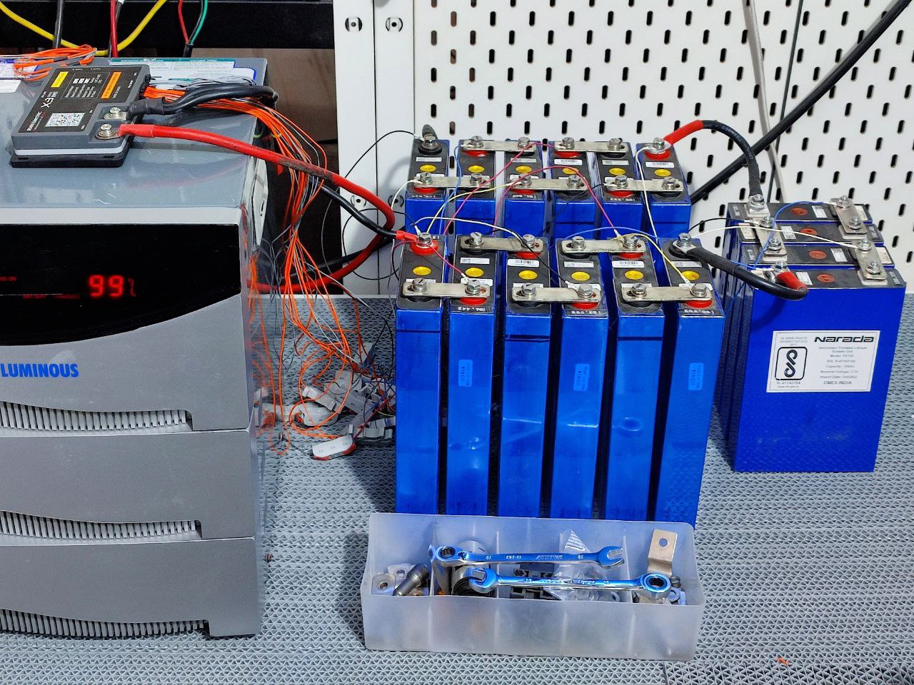
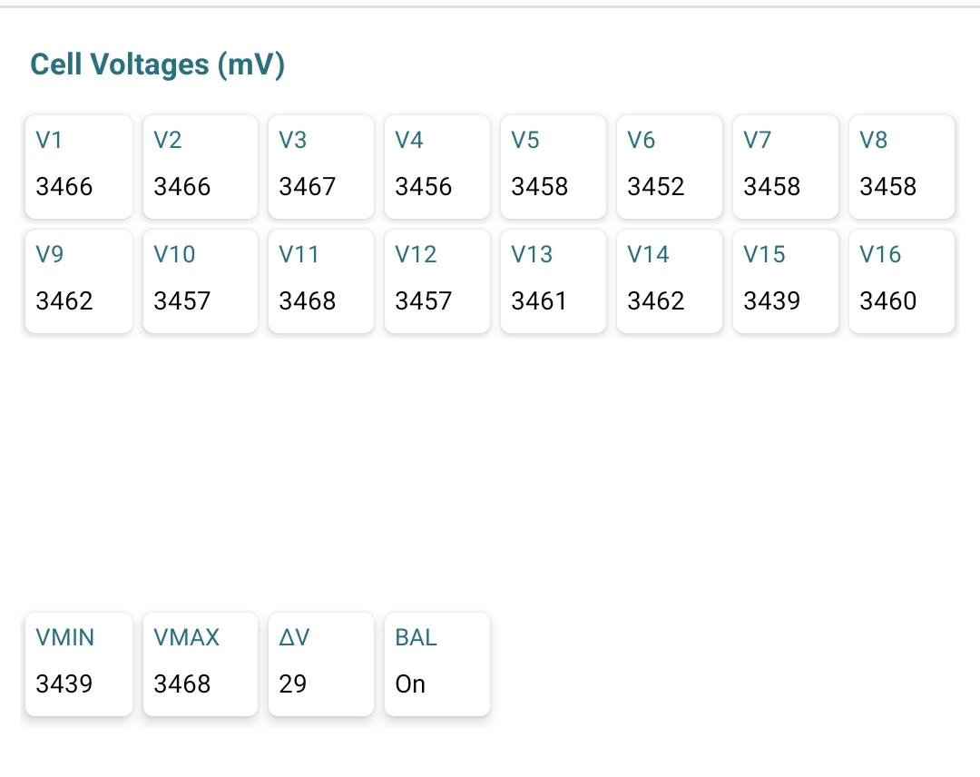
Anyway, I’ve been doing a rough capacity test, to see if there’s been any degradation since I got these cells. I’ve put on a ~20A continuous load for almost five hours now and all of the cells are still above 3V, it’s doing great. I’ll do a proper capacity test when I’ve finished building this, in a month or three.
To note: My automation flows no longer work, the low battery shutdown and safe startup etc, they relied on the lead acid battery monitors.
I’ll need to work out a way to get communication from this BMS to MQTT and Node-RED, preferably through the can bus interface, or modbus or uart. I’ve done uart to mqtt before, but I’d really like to use the can bus interface because it’ll auto broadcast. But that’ll happen after I regrow some brain cells. I’m just relieved that I can stay online now during extended power outages.
Replying in this thread so the other doesn’t get derailed.
Yes, that is one of the things I’m going try out.
Yes, that’s the plan, I’ll be doing efficiency calculations to compare before/after.
The BMS is potted/sealed. This BMS is designed to protect against >500A short circuits, the datasheet says response time for short circuits is 8 microseconds.
Forgot .. the 230v line will be copper . You just need to rewind the out 24v core . If you are good with transformer winding you could probably do it within 1000 rupees .
It’s been a productive night! I started work around midnight and finished at 6 (I work slow).
Here’s a recap. But first a story, as is expected.
With the lead acid batteries, I was able to track/monitor/notify about power outages by the fact that the inverter float charges the batteries at 13.9x4 so when power is cut, that drops immediately down to 13 and lower. Those IoT lead acid battery monitors were pretty helpful:
But that same float voltage works out to be 13.9/4 = 3.475V per lifepo4 cell, which is very close to their resting voltage, so I can’t use that method here.
I could just directly monitor live mains ac but I wanted a safer, non-invasive way so I got the idea of using a current transformer clamp, a ct clamp.
If there’s current flowing, then we have power. If it drops to below 1A, then power went out and we’re on battery power (there’s some leakage by the inverter so it’s never 0).
That’ll be perfect, in theory.
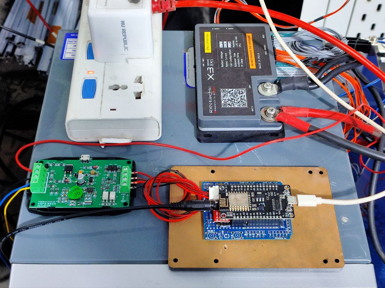
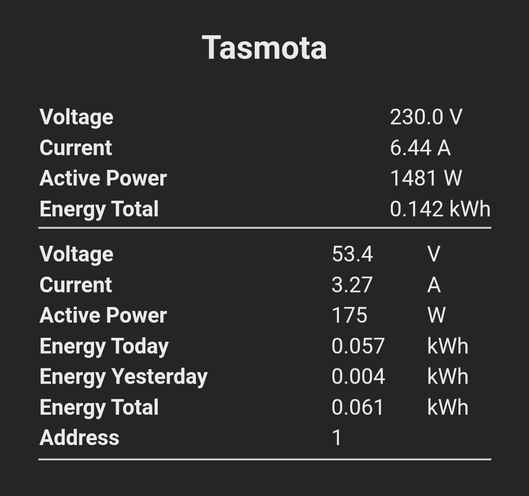
Next, I want my own coulomb counter, something to track voltage, current, state of charge, state of health — independent of the BMS.
The idea is to collect data with Tasmota transmitting to MQTT, receive and process by Node-RED, store in InfluxDB and display in pretty graphs with Grafana.
As with everything I like to do, all logic will be server-side (SoH, SoC, etc).
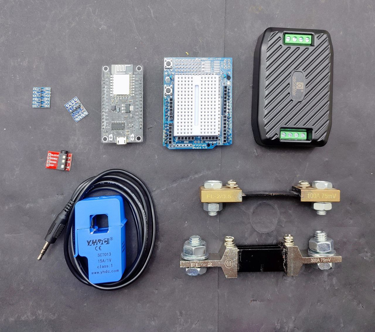
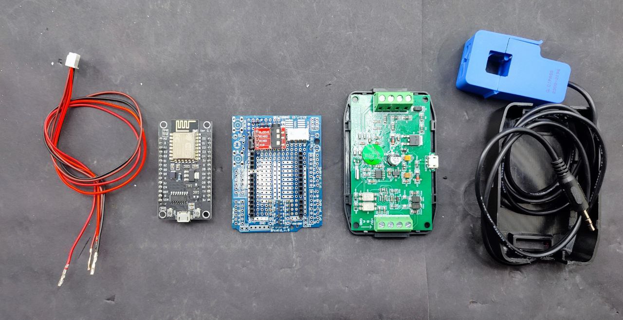
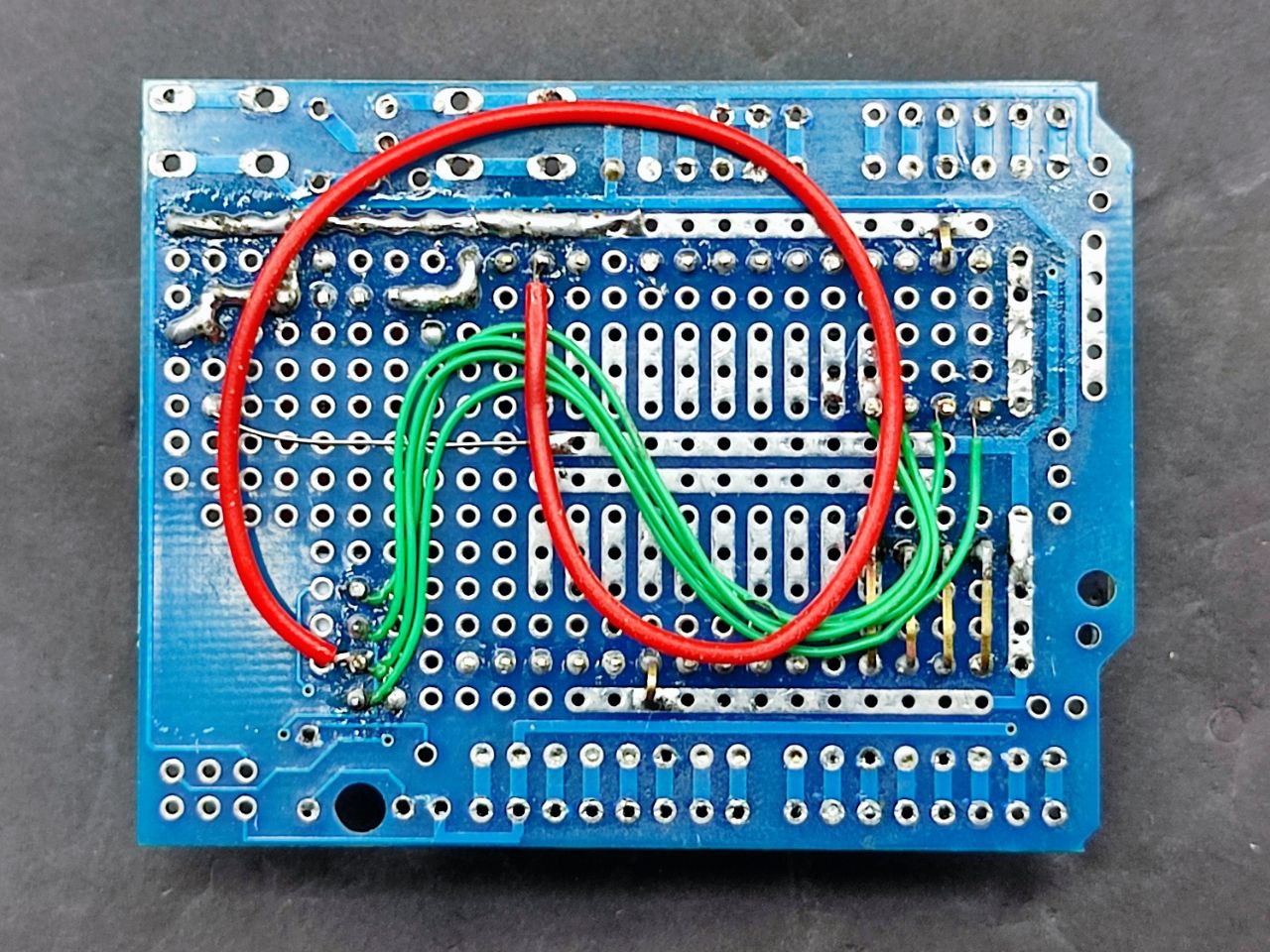
There’s an arduino protoshield, a nodemcu, the pzem module, level shifters to communicate with the pzem module, the ct clamp, and a 3.5mm breakout board to connect to the ct clamp.
I chose a 15A/1V clamp because the inverter can’t handle more than 3000W.
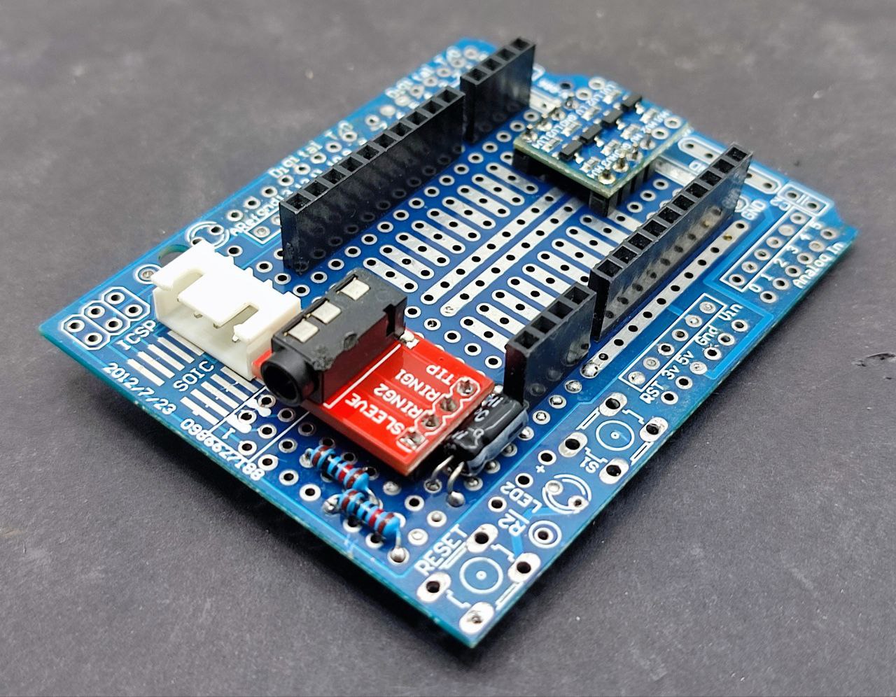
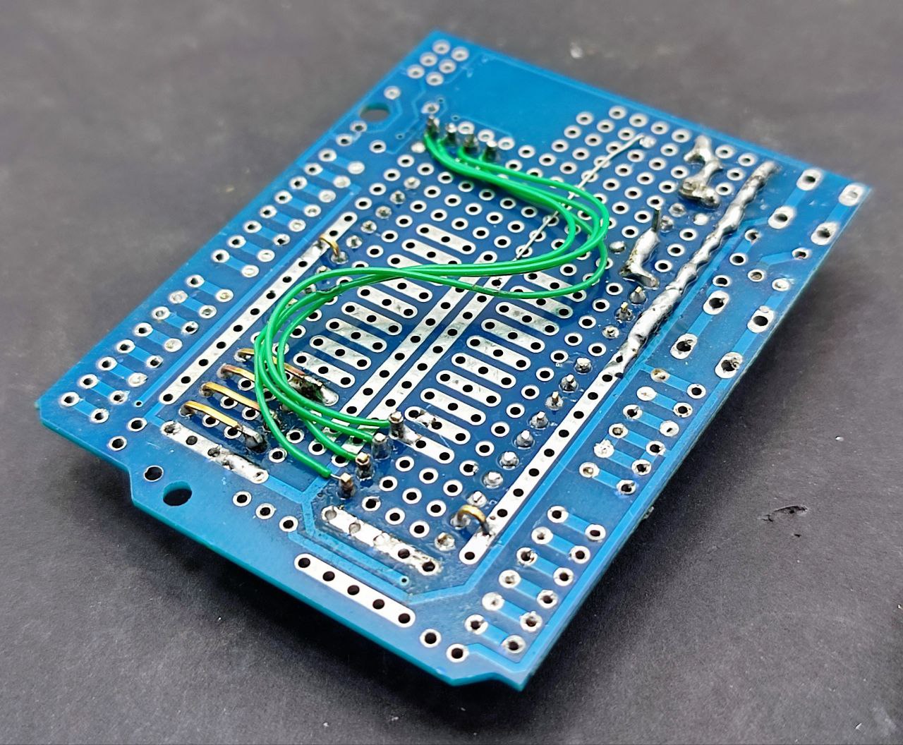
The ct clamp has two connections, one directly goes to the ADC pin and the other is used to bias the signal to positive with a voltage divider and a capacitor.
The 4 pin jst connector is for serial communication while the level shifter is at the back. It’s not absolutely necessary, there are simpler ways, but it was just Rs 13.
I didn’t have any 15 pin female headers so I used 10pin and 4pin.
I needed to adjust the multiplier value for the ct clamp since the default values are for a 20A/1V transformer. AdcParam is now deprecated in tasmota, replaced by AdcGpio so here’s the command: ADCGPIO 0,1610,0.23,0
Would’ve been simpler to just get a 20A/1V clamp, it took a while to figure out the new value and also that I need to set the ADC gpio to CT POWER and not CT CURRENT.
The logic in the nodered flow is if current > 1 then charge = true and if current < 0 then discharge = true and power status is based on whether we’re charging or discharging
This logic is necessary because the pzem module cannot tell us which way the current is flowing, it’ll just tally up both charging and discharging and give us a total energy reading. It’s a little limited in that way.
The BMS can tell us, but I want an independent system.
Here we go, five hours of sleep is plenty (I’ll sleep more when I’m dead).
The pzem module communicates through modbus, a mature and well known protocol, but it’s half duplex and since I don’t really need everything modbus offers, I’ll be using serial uart.
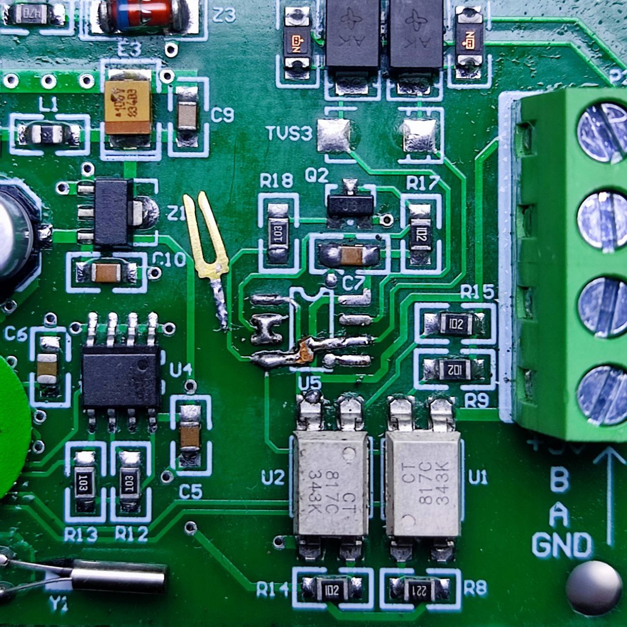
Fortunately this means it’s as easy as yeeting the MAX485 chip off the board and connecting the input pads to the output pads:
This still maintains the optical isolation, which is great.
Except it took a while to figure out that the module requires you to provide 5V, which makes sense, how else would you power the optoisolators when there’s no 5V regulator on board?
Except no documentation anywhere tells you that you need to provide 5V, so that was fun.
So last night was spent coming up with the logic for State of Charge, State of Health, Cycles — about 90% of that was figuring out how to structure the data and what variable names would sound cool, the other 10% was trying to remember Javascript syntax, ha.
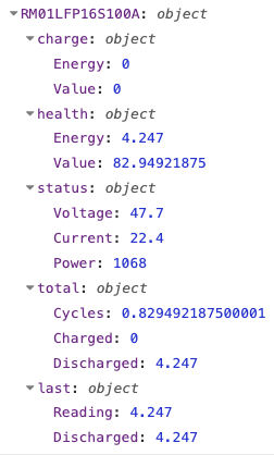
The top level object key is unique name of the battery set in tasmota, for when I have multiple batteries. RM01 is Rack Mount #1 and the rest is self-descriptive, LFP 16S 100Ah.
“charge” is State of Charge, currently zeroed out since I discharged the battery down to 48V
“health” is State of Health, currently measuring 4.25kWH (out of 5.12) or 82%, probably due to less than ideal connections (Current value is between half an amp to 1amp less than what the bms reports) — also I need to fix the rounding on the percentages after I find my brain
“status” is the current battery measurements
“total” is cumulative kWh in and out of the battery along with cycle count. Cycles are calculated against last known State of Health value, for this first discharge it was against the rated capacity, but now onwards it’ll be against this new value of 4.25kWh. I’ll be scheduling/planning a State of Health calibration (discharge down to 48V) about once every month if we don’t get any long outages.
“last” is data I need to be stored for calculations, reading is total energy reported by the pzem module and discharged is how much energy is currently being discharged, uninterrupted. A full discharge down to 48V gives us the current state of health.
Of note is that the battery name set in tasmota will autoconfigure battery configuration in the code. I’m only going to consider low voltage cutoff at 3V per cell or 48V for this pack even though you do have some energy left over (between 5% and 10%), this will be the trigger point for a safe shutdown of the homelab.
This means state of health will be capped at about 90% to 95% of actual capacity, which I’m fine with. You could think of it as “reserve” in a petrol tank, I guess.
Data retention strategy: tasmota sends data through MQTT every 10 seconds, Node-RED will then record it to InfluxDB every minute, which is then averaged out to every hour after 30 days.
I think that covers the logic bit. As far as I can tell, this is a more useful set of data than what something like a Victron Shunt provides, at least at first glance. If I’m missing something, let me know.
So this is Version 1.1 of the battery, completed. I’ll add per-cell battery monitoring later on, after these cells are in some kind of frame/cage.