INTRODUCTION
The Altec Lansing MX 5021 speakers have been here for a while. Tauted to be one of the best speakers in the 2.1 genus second only to the legendary Klipsch Promedia 2.1, the Altec still packs a punch when it comes to performance. Audiophile grade music and one need not spend an arm and a leg on the speakers!

Although the MX 5021 was launched at a staggering price of about 11k and thereabouts, there have been revisions in the motherboard, the crossover circuitry, the mid-woofers and sub-woofer design for the speakers which were launched post 2007. There’s also been a significant reduction in the price for which the speakers retailed at the time of launch and today! You can get a set for close to 6.5k (depending on where you’re located!).
There have been a couple of mods attempted on the MX 5021 by audio DIY enthusiasts around, floating on the web (Eg. Jimmy from Malaysia has put up an article on his blog; read it here: Jimmy’s Junkyard Blog Archive Inside Altec Lansing MX5021: Amplifier Mod , our own TE member Sangram has compiled an article which prompted me to go ahead with this mod! Both these mods have been attempted on the first-gen MX 5021.)
Most mods are inexpensive and would suggest replacing the stock OPAMPS and the stock capacitors which get along the way of the signals as they cause significant degradation thanks to the quality of the capacitors/OPAMPS used. Attempting the mods are pretty easy, provided you’ve touched a soldering iron before and have a li’l DIY intellect hidden within yourself! Awaken thyself monsieur!
Before we get started with the mods, let me be very clear with 2 things. Attempting the mod WILL void the warranty of the speakers (it’s going to be Rashi Peripherals ultimately, so think twice before you’re at it! Dont hold me responsible for anything that might go wrong) and I shall not touch the hard-core electronic aspects of the mod being attempted.
[BREAK= The MX 5021 ver. 2!!!]
Like I said before, the MX 5021 has underwent some changes compared to the first lot which retailed since the launch. IINM the newer lots went into retail as early as mid 2007. Let me highlight a few changes. The newer batch of MX 5021 has a totally redesigned subwoofer and midwoofer cone. Check out the older one:

and the newer one:

The newer ones have a smooth spherical cone for the subwoofer and the midwoofers with no flat surface in the centre. The removable plastic shroud for the subwoofer has been changed as well.
The crossover circuitry has been changed! Take a look at the one in the older lot (from Jimmy’s blog):

And here’s the newer one:

There’s one less inductor and two less capacitors compared to the newer crossover circuitry. I’ve no clue as to if this would have made a significant change in the quality of the sound.
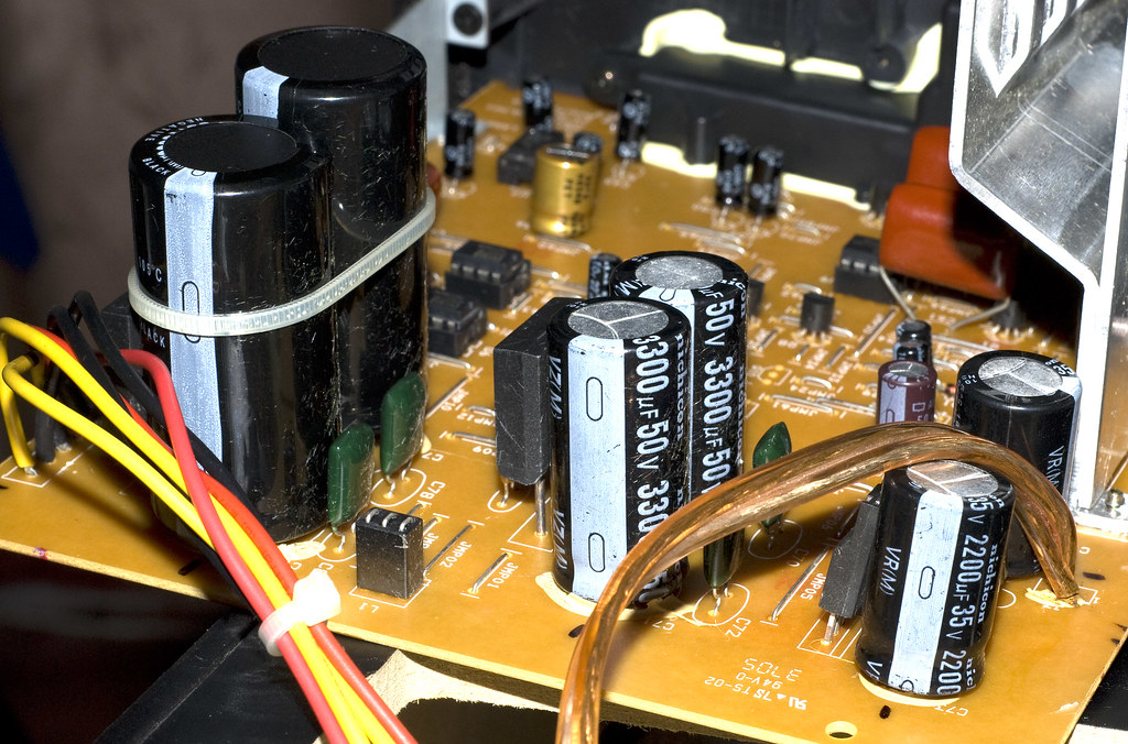
Finally here’s the mainboard of the speakers. This belongs to the older lot (taken from Jimmy's blog):

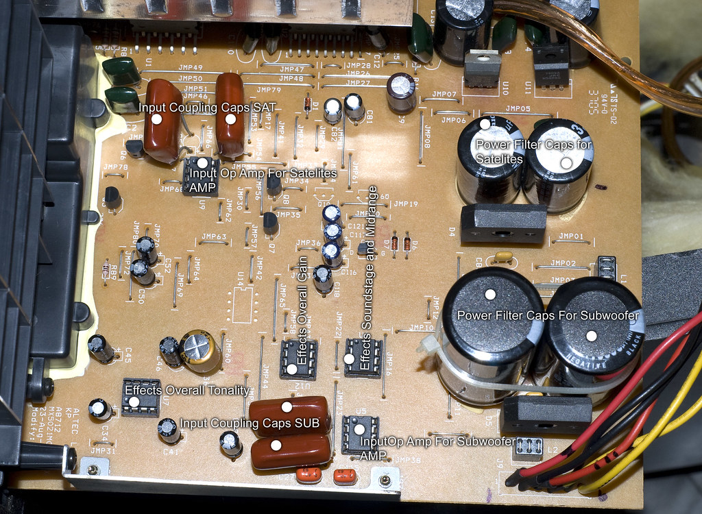
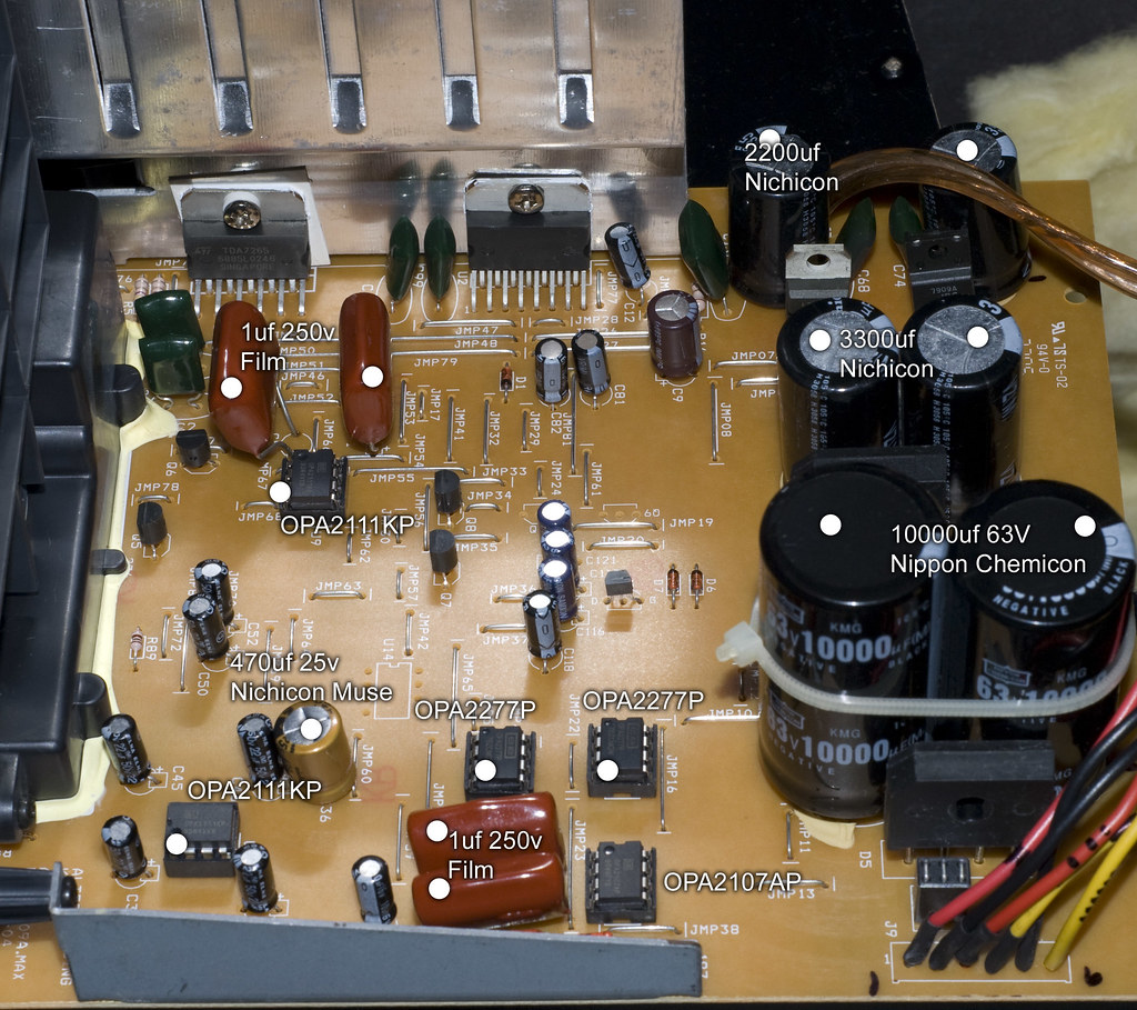
And here's the newer one:

Most of the components are intact minus one opamp! Notice carefully, and you’ll find the opamp U14 is missing. This could prove beneficial since lesser the opamps lesser is the distortion. The missing opamp suggests that it might’ve been replaced with some other components.
Apart from these changes, both the older and the newer batches of the MX 5021 have been blessed with components made of substandard quality! The capacitors deserves a mention here – brands like Samcon, Samxon etc. are probably the locally available ones which if replaced with the Nichicon, Nippon Chemicon, Panasonic FC, Kenwood, Sanyo equivalents could make a significant difference to the sound!
Let’s get started! hyeah:
[BREAK= PREREQUISITES]
You’ll need the following stuffs handy before attempting the mod:
1. Soldering Iron - 25w (Soldron preferably)
2. Flux core solder reel.
3. Desoldering braid/wick.
4. Wire cutter/stripper and hobby knife.
5. Philips head screwdriver.
6. Tweezers.
7. A small bottle of solvent (Iso-propyl alcohol/acetone) and cotton swabs.
8. Sand-paper (medium grade like Gr. 120).
9. Soldering iron stand.
Most of us must’ve come across the soldering iron before! Probably during those 11th- hour electronics and instrumentation project submissions during the 3rd yr of graduation or the Science projects during high-schooling or sometimes even much before (that said I bought my first 30-Rs wala soldering iron during my 7th grade schooling! My first DIY circuit was a UM66 - IC based melody generator. Google for UM66!).

1. We’ll need a good soldering iron. India’s most trusted brand of soldering irons are probably the Soldron makes. Rs. 130 could get you a 25W decent one with a good element which would last for years. (FYI the Soldron that I used for this mod was bought 6 yrs back and still kicks arse!) I’d advise you to stay away from the local cheapo makes and stick to a good iron before you get started.

2. We’ll need a reel of solder. It is advisable to go with a reel of flux-core solder since this could eliminate the need of using flux (it is called flux-core because the core/heart of the solder-wire contains flux). Lead-free solder (IINM it’s called silver solder) is available which’s slightly expensive but produces the best results. As such, this would not make a significant change to the performance of the mod either so the flux-core solder for around 30-40 bucks serves the purpose.

3. In order to remove the solder off the board, we’ll need a desoldering braid. This is just a mesh of copper wire which sucks the solder from the board (due to capillary action) when the hot soldering iron is applied on the braid kept on top of the soldered leg of any component. A desoldering gun, an expensive alternative might sometimes suck the tracing off the board itself (I’ve had experiences before) hence I’d suggest otherwise. The desoldering braid might cost you 10-15 bucks.

4. We’ll need few tools handy such as the wire cutter, wire stripper and a hobby knife. The local electronics shop in your neighbourhood would stock these! Check if you can get hold of a wire stripper-cum-cutter as shown in the pic above.

5. A Philips head screw driver is a must to unscrew the subwoofer, the mainboard panel and the satellite enclosures. Take a look at the back of the satellites. If you’re getting a tool-kit as such, make sure that the attachments are lengthy enough so as to go through the holes of the satellite speakers’ on the back-side. The ones with the magnetic attachments generally do not go this way and might get stuck!

6. If you can get hold of a tweezers, nothing like it! Instead of pulling the component by hand, the tweezers could help you to gently pull-out one leg of the component at a time.

7. A small bottle of a solvent such as iso-propyl alcohol or acetone and a couple of cotton-swabs would help to remove the excess flux from the board after the soldering is done. Would result in a clearer and a more professional mod!
8. A sheet of sand-paper (any medium grade would do; something like grade 120) would be helpful in buffing the legs of the components so that the solder could stick easily to the leg and the board.

9. Lastly we’d need a stand to rest the soldering iron while not in use. Costs as much as 50 bucks for a simple spring-type stand with a sponge in the end.
[BREAK=COMPONENTS reqd]
Apart from the things I’d listed out, we’ll need these components to get the mod done:
1. NE5532 opamps – 3 nos + 3 standby – Rs. 15 each
2. 22uF or 47uF 50v – 6 nos + 6 standby - Imported from Digikey, US – Panasonic FC/Kenwood/Chemicon/Nichicon/Sanyo etc.
3. .47uF 250v – 2 nos – Thermax – Rs 50 each
4. .47uF 63v – 2 nos – Vishay MKP - Imported from Digikey, US
5. 15 AWG/40 or 60 taar wala (strands!) wire - 1m - Local make
Although I’ve suggested the same no. of components for standby, one need not necessarily get the same quantity. If you end up having surplus stuff towards the end of a successful mod, have it given to someone else for another mod.

[BREAK= MODDING]
We shall adopt a step-by-step procedure, attempting one mod at a time and verifying the same after it is done so that any error could be easily traced.
We shall:
1. Mod the satellites first, one at a time (check them after each mod!),
2. Recap the mainboard (check them!),
3. Swap the OPAMPs (check them!),
4. And finally, re-wire the stock subwoofer cable (and seal the deal!).
[BREAK= MODDING THE SATELLITES]
Switch on the soldering iron and let it rest on the stand. Unscrew one of the satellites’ enclosures (6 screws) and pull it out gently. You must be noticing the wires glued to the back side of the enclosure and the crossover circuit board screwed to it. Something like this:
Unscrew the board. The circuit diagram should look something like this:

We shall bypass the crossover by soldering the Vishay MKPs (.47uF 63v) parallel to the 4.7uF 50v cap. i.e

Clean the legs of the caps using the sand-paper to reveal the copper lead. The legs of the caps are small, so ensure that it is soldered in such a way that you could screw the crossover board back on place and close the enclosure.

These caps don’t observe polarity so soldering either lead is fine. This pic should help:

Now, solder 2 47 uF 50v caps back-to-back in series, i.e 2 -ve leads together so that we get 2 free +ve leads. [+ve ----||----||---- +ve] This way, the polarity of the caps becomes void and we get a net capacitance of 23.5 uF 100v across the 2 +ve leads. We've 2 solder the 2 +ve leads to the terminals of the bottom mid-woofer. The final crossover circuitry should look like this:

Attempt the same mods for the second satellite speaker. Once the mods are done, clean the soldered connections using a swab dipped in IPA. Screw the crossover circuit back and close the enclosure and screw it. Plug the wires and the connections and play a high quality FLAC on the foobar or your music player.
RESULT: You should be probably hearing some unheard vocals/instruments once the mod is successfully attempted. Basically the treble is going to be clear.
[BREAK= RECAPPING THE BOARD]
Remove the plastic cloth shroud from the subwoofer unit (if you’ve one in place). It must’ve been glued but a slight pull should get that out. Now removing the silver ring on the subwoofer could be a bit tricky! The ring is also glued to 4 holes around the subwoofer. Try inserting your finger nail and see if you can separate it. If it’s hard chuck it! Now very carefully insert the edge of the hobby knife and gently pull the ring from one side. Do the same from the opposite side. While at it, ensure that you don’t scratch either!
Unscrew the subwoofer. It’s going to be heavy so hold the sub while unscrewing the last screw! Notice the really thin stock cable for the sub? Apply the soldering iron on the leads and remove the sub and place it somewhere.
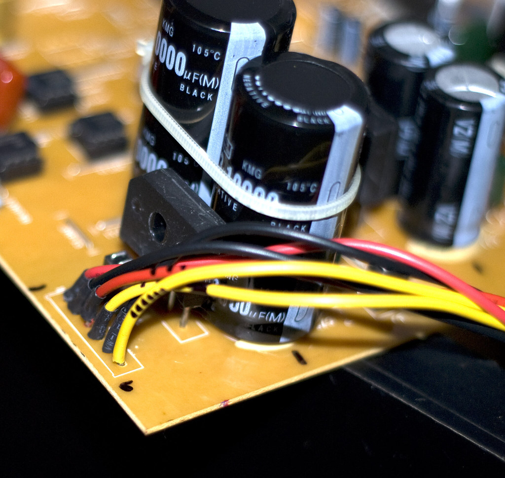
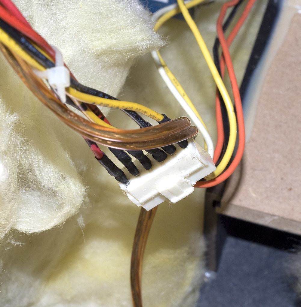
Notice a 6-pin power connector glued to the board?
Now, comes the hardest part (at least I felt so!) of the entire exercise. Unplugging this power connector! The thing’s *sigh* glued to the board. Take out the hobby knife and start slicing the glue gently. If required place the tip of the hot soldering iron on the edge and melt the glue. Try unplugging it at regular intervals. The connector can easily take some abuse. Dont worry about chopping it off; that’s not going to happen if you’re careful enough! This should consume some of your elbow grease and once it’s off, voila!hyeah:

Unscrew the mainboard (12 screws) on the back of the subwoofer enclosure and gently pull it off. You should notice the yellow fluffy thingy in there?

I believe its glass wool (although the usage isn’t known to me. All I know is it’s a good thermal insulator at high temps!).
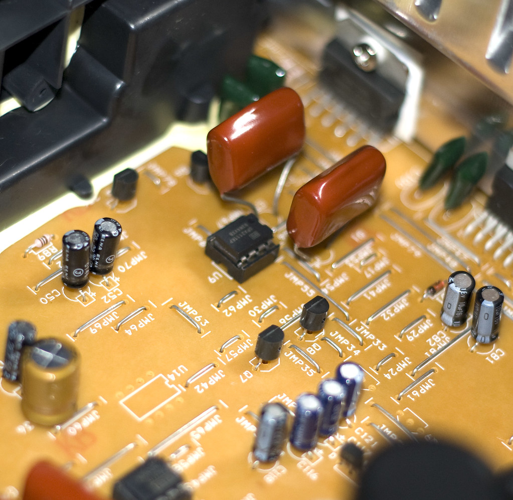
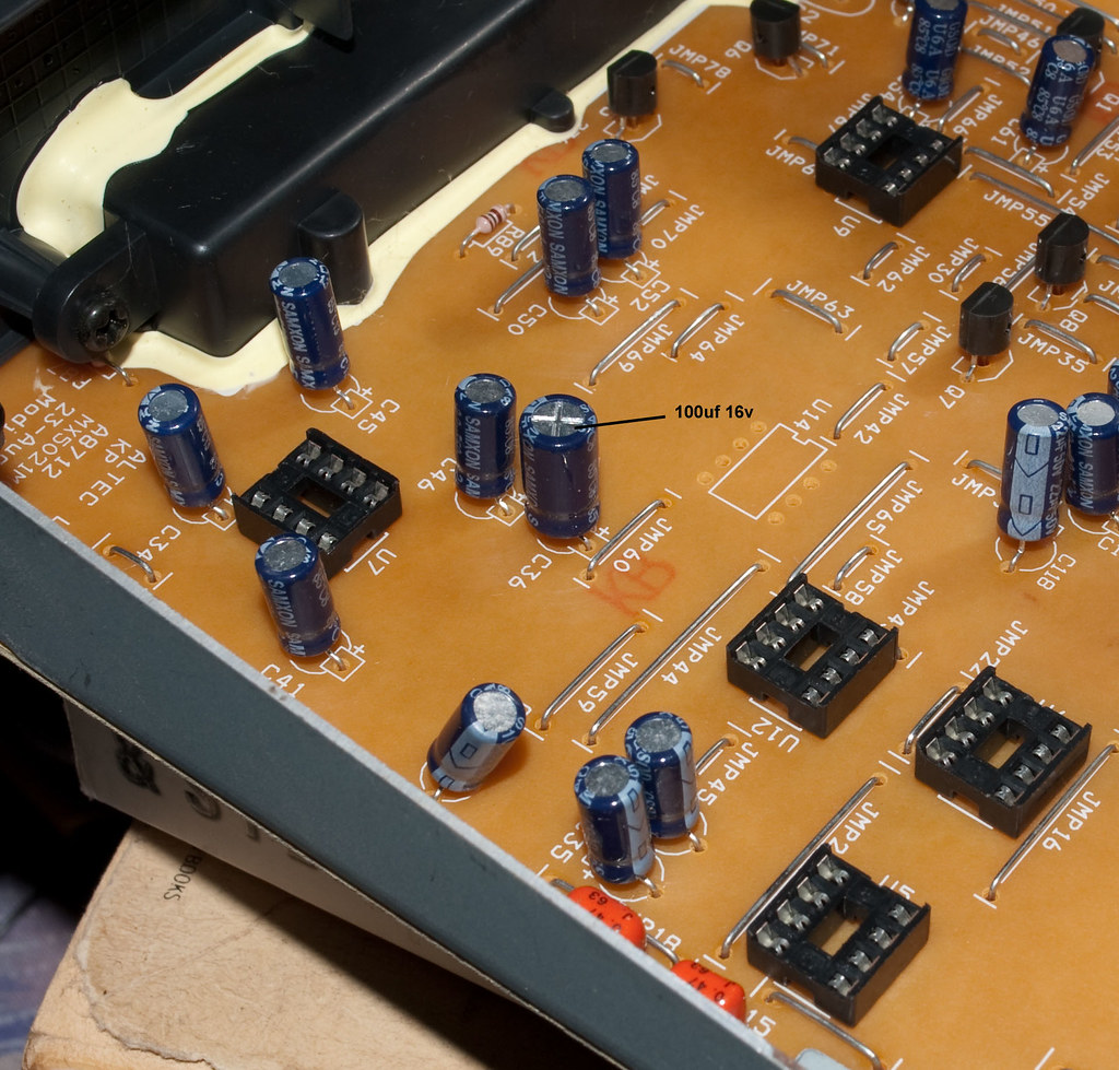
Rest the mainboard on a table and carefully spot the capacitors and chips to be replaced and mark the legs on the soldering side of the board to desolder the right one!

The stock caps need to be replaced with the values mentioned below:
Cap. Nos – Stock Value – Replace with
C61, C54 – 1 uF 50V – Thermax .47uF 250v
C50, C52 – 2.2uF 50V – 22uF/47uF 50v
C45, C34 – 22uF 50V – 22uF/47uF 50v
C41, C46 – 2.2uF 50V – 22uF/47uf 50v
Note: The above values of the capacitors might be different for the older lot of MX 5021 systems. In any case the replacement values hold valid for both the batches.
For desoldering the component, place the strip of the desoldering braid/wick on top of the soldered component-leg and gently apply the tip of the soldering rod.

The fumes coming indicate that the solder lead has been sucked to the braid. This would reveal the hole and the component leg. Remove one leg using the tweezers held to it. The process’d hardly take 10-15 seconds for each component.
Repeat the process for 8x2 = 16 leads in total!
Once done, replace the capacitors C50, C52, C45, C34, C41 & C46 OBSERVING THE POLARITY!!! (Usually the longer lead is +ve and the –ve lead is generally marked on the capacitors). The Thermax caps dont’ve polarity so either way is fine.
While soldering the cap (any component i.e), the most basic practice adopted is to hold the soldering rod in one hand and have the reel of solder on the other and gently feed the solder to the tip of the iron, melting the solder and depositing it on the surface, leaving a good deposit.

Feed enough lead so as to ensure a good amount is deposited. Excess amount is undesirable anyway and a deficient amount wont secure the component properly.
Once all the 8 caps are soldered, clean the soldered connections using the swab dipped in IPA, plug the 6-pin connector and solder the stock subwoofer cable to the sub, screw the sub partially, plug the rest of the connections, play the FLAC again.
RESULT: The sound could be a bit bland initially since the capacitors have to burn in. Once they’ve burned in after 10~12 hrs, the depths and the mids should be improved. As a whole the soundstage expands and the overall quality of the sound must’ve improved.
NOTE: Replacing all the caps on the mainboard and the satellite crossovers with HQ caps of the same value (read Panasonic FC/Kenwood/Sanyo make!) should improve the overall SQ but at an expense! We’re OTOH aiming at a VFM upgrade.")
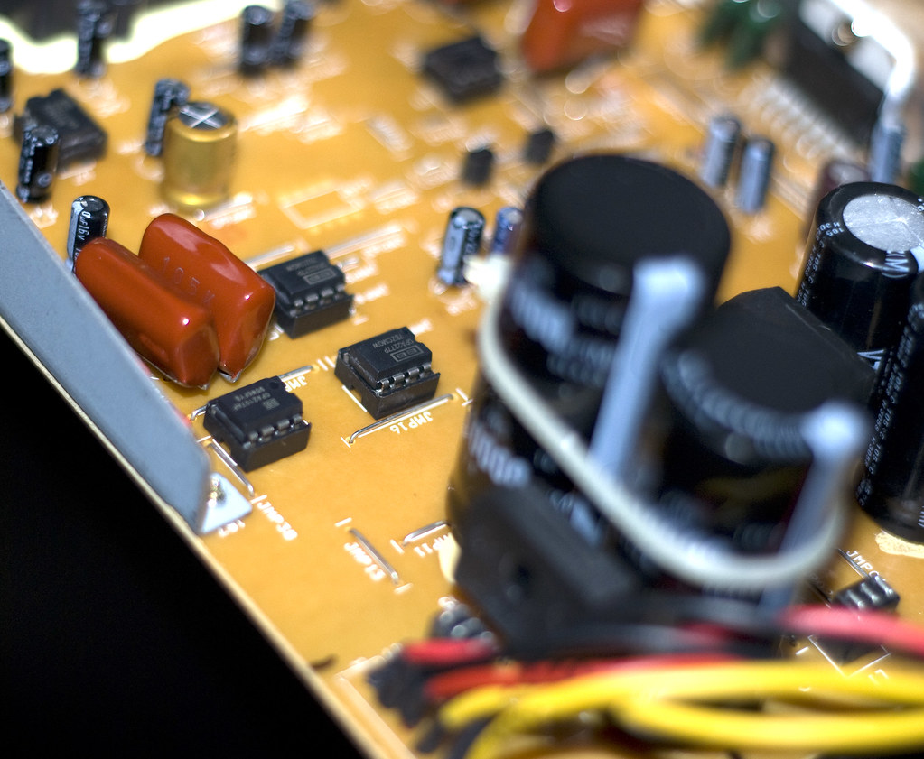
[BREAK= SWAPPING THE OPAMPS]
Unscrew the sub, desolder the cable, unplug the pwr connector and remove the mainboard out of the enclosure (this’s a boring procedure but helps eliminate any errors and trace them if one creeps in!).
Notice the chips U7, U12 and U9? Those’re the ones to be swapped (Peeps having the older lot of the MX should take note of the U14 as well which’s missing on the newer ones! This one is to be replaced along with the other 3!).
Use the desoldering braid to suck in the solder from the 8 legs of all the chips. One chip at a time! The tracing is delicate.
CAUTION: DO NOT TRY TO PUSH ANY LEG OF ANY COMPONENT TOWARDS THE BOARD. THIS WOULD REMOVE THE TRACING OFF THE BOARD!

The chips would come out quite easily once all the solder has been sucked into the braid.

For the replacements, I’ve used the locally available NE5532 opamps. Other alternatives include the OPA 2134, OPA 2132, OPA 2107, THS 4032, AD 8066 etc. Availability could be an issue for the rest of the chips.
Ideally, the best way to solder the chip is directly to the board or solder the 8-pin IC sockets to the board and plug the ICs into the sockets. I’d advise you to stay away from the locally available IC sockets since they induce stray impedance at the contacts and negate the quality. If you’re adventurous enough, you can get a bunch of machined IC sockets with gold-plated leads for Rs. 100 each and play around with different opamps.")

While soldering the chip, you need to be cautious enough not to solder all the legs of one chip at a time. Overheating could damage the chip quite easily rendering it useless. So here’s a simple tip: Put all the chips on the board in place and solder one lead of each IC turn-by-turn at a time.
Do mind the direction of orientation of the chips. The groove on the chip should match the groove on the board! Take a look at the pic:

Counter-clockwise it goes from pin # 1 to pin # 8.
So get going with soldering turn-by-turn one lead of each IC at a time!
1st lead of U7, 1st lead of U12, 1st lead of U9,
2nd lead of U7, 2nd lead of U12.... go on & on...
............................................................................
8th lead of U7, 8th lead of U12 and finally the last lead of the last chip U9.
And you’re done with the soldering. It should be done slowly and steadily. Ensure that the hand is steady and does not shiver while at it. First time users might find it a bit hard but you’ll get over it! As always, do not forget to clean the connections using the swab dipped in IPA!
[BREAK= REWIRING THE STOCK SUB CABLE]
This is the concluding mod. You’d notice how thin the stock subwoofer cable is (akin to the fan cables!). The connector should be glued to the board. Slice the glue using the knife. Desolder the connector from the underneath of the board and remove the connector.
For replacing the stock cable, around 50cm of the cable should be sufficient. Strip the cables at the 2 ends and use the sand-paper to buff the strands of the wire to reveal the copper colour on the strands. Once done, apply some generous amount of solder on the cable leads to pre-solder the cable leads. Use sufficient amount of solder to ensure that the leads look like one fat single strand!
To solder the cable on the board, scratch the green coating on the adjacent rails of copper tracing as shown:

Apply some solder on the board first and then solder the cable leads. There should be sufficient solder on the cable leads and the board combined to ensure a secure solder on the leads.

In order to remove the stress from the cable being bent, I used a small piece of 3M double sided tape (source: KMD) and stuck the cable on the board securely. This should prevent any movement of the cable.

That concludes all the mods! Secure the mainboard back in place, screw it to the enclosure, connect the 6-pin pwr connector to the board, solder the 2 leads of the subwoofer cable to the subwoofer

and finally seal the subwoofer back in place.
Switch on the pwr and play the FLAC and notice the changes!
RESULT: The bass’s have improved. Tight and punchy. The subwoofer cone does not keep doing the flak-flak thingy at low frequencies compared to before. The SQ should be improved overall.
Once everything’s rightly done, seal the ring of the subwoofer and cover it with the plastic-cloth shroud (or as you wish to keep it!).
[BREAK= FINAL WORDS]
Guess that's enough for now! I hope it was a wonderful experience attempting the mod by yourself. The results would be quite obvious. In addition there’re a couple of mods you can attempt like using a pair of RCA jacks for input instead of the 3.5mm connector. You can as well try some other opamps which has already been suggested.
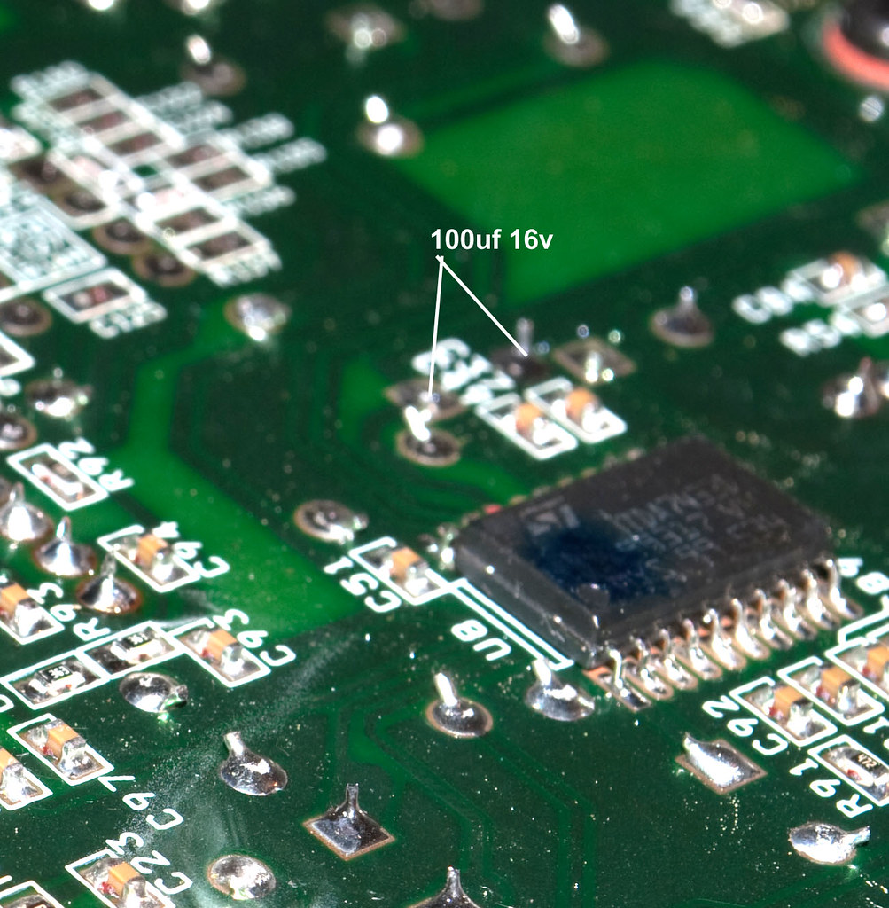
There’s a mod which I left out: adding a pair of capacitors to the ground of the power ICs TDA 7265 datasheet and solder two 10uF caps to each supply pin and ground. I could not find time for those hence left it. Once its done I’ll surely post about the same here and append the guide.
I would like to express my heartfelt thanks to Sangram, Bikey, his friend, Vaibhav, his cousin, Kichy and inevitably the almighty to have me helped to get the right stuff at the right time, support me through the mod, to have shown patience to read all those annoying PMs, calls, SMSs and what not.
I hope you guys found the article interesting. Brickbats, comments, credits welcome.
For TE,
Gunman aka Ganesh.
References:
1. http://www.techenclave.com/audio-zone/mx5021-modding-99129.html
2. Jimmy’s Junkyard Blog Archive Inside Altec Lansing MX5021: Amplifier Mod
3. Jimmy’s Junkyard Blog Archive Altec MX5021 Speaker Mod
The Altec Lansing MX 5021 speakers have been here for a while. Tauted to be one of the best speakers in the 2.1 genus second only to the legendary Klipsch Promedia 2.1, the Altec still packs a punch when it comes to performance. Audiophile grade music and one need not spend an arm and a leg on the speakers!
Although the MX 5021 was launched at a staggering price of about 11k and thereabouts, there have been revisions in the motherboard, the crossover circuitry, the mid-woofers and sub-woofer design for the speakers which were launched post 2007. There’s also been a significant reduction in the price for which the speakers retailed at the time of launch and today! You can get a set for close to 6.5k (depending on where you’re located!).
There have been a couple of mods attempted on the MX 5021 by audio DIY enthusiasts around, floating on the web (Eg. Jimmy from Malaysia has put up an article on his blog; read it here: Jimmy’s Junkyard Blog Archive Inside Altec Lansing MX5021: Amplifier Mod , our own TE member Sangram has compiled an article which prompted me to go ahead with this mod! Both these mods have been attempted on the first-gen MX 5021.)
Most mods are inexpensive and would suggest replacing the stock OPAMPS and the stock capacitors which get along the way of the signals as they cause significant degradation thanks to the quality of the capacitors/OPAMPS used. Attempting the mods are pretty easy, provided you’ve touched a soldering iron before and have a li’l DIY intellect hidden within yourself! Awaken thyself monsieur!
Before we get started with the mods, let me be very clear with 2 things. Attempting the mod WILL void the warranty of the speakers (it’s going to be Rashi Peripherals ultimately, so think twice before you’re at it!
Dont hold me responsible for anything that might go wrong) and I shall not touch the hard-core electronic aspects of the mod being attempted. [BREAK= The MX 5021 ver. 2!!!]
Like I said before, the MX 5021 has underwent some changes compared to the first lot which retailed since the launch. IINM the newer lots went into retail as early as mid 2007. Let me highlight a few changes. The newer batch of MX 5021 has a totally redesigned subwoofer and midwoofer cone. Check out the older one:
and the newer one:
The newer ones have a smooth spherical cone for the subwoofer and the midwoofers with no flat surface in the centre. The removable plastic shroud for the subwoofer has been changed as well.
The crossover circuitry has been changed! Take a look at the one in the older lot (from Jimmy’s blog):
And here’s the newer one:
There’s one less inductor and two less capacitors compared to the newer crossover circuitry. I’ve no clue as to if this would have made a significant change in the quality of the sound.
Finally here’s the mainboard of the speakers. This belongs to the older lot (taken from Jimmy's blog):
And here's the newer one:
Most of the components are intact minus one opamp! Notice carefully, and you’ll find the opamp U14 is missing. This could prove beneficial since lesser the opamps lesser is the distortion. The missing opamp suggests that it might’ve been replaced with some other components.
Apart from these changes, both the older and the newer batches of the MX 5021 have been blessed with components made of substandard quality! The capacitors deserves a mention here – brands like Samcon, Samxon etc. are probably the locally available ones which if replaced with the Nichicon, Nippon Chemicon, Panasonic FC, Kenwood, Sanyo equivalents could make a significant difference to the sound!
Let’s get started!
hyeah:[BREAK= PREREQUISITES]
You’ll need the following stuffs handy before attempting the mod:
2. Flux core solder reel.
3. Desoldering braid/wick.
4. Wire cutter/stripper and hobby knife.
5. Philips head screwdriver.
6. Tweezers.
7. A small bottle of solvent (Iso-propyl alcohol/acetone) and cotton swabs.
8. Sand-paper (medium grade like Gr. 120).
9. Soldering iron stand.
Most of us must’ve come across the soldering iron before! Probably during those 11th- hour electronics and instrumentation project submissions during the 3rd yr of graduation or the Science projects during high-schooling or sometimes even much before (that said I bought my first 30-Rs wala soldering iron during my 7th grade schooling! My first DIY circuit was a UM66 - IC based melody generator. Google for UM66!
).
1. We’ll need a good soldering iron. India’s most trusted brand of soldering irons are probably the Soldron makes. Rs. 130 could get you a 25W decent one with a good element which would last for years. (FYI the Soldron that I used for this mod was bought 6 yrs back and still kicks arse!
) I’d advise you to stay away from the local cheapo makes and stick to a good iron before you get started.
2. We’ll need a reel of solder. It is advisable to go with a reel of flux-core solder since this could eliminate the need of using flux (it is called flux-core because the core/heart of the solder-wire contains flux). Lead-free solder (IINM it’s called silver solder) is available which’s slightly expensive but produces the best results. As such, this would not make a significant change to the performance of the mod either so the flux-core solder for around 30-40 bucks serves the purpose.
3. In order to remove the solder off the board, we’ll need a desoldering braid. This is just a mesh of copper wire which sucks the solder from the board (due to capillary action) when the hot soldering iron is applied on the braid kept on top of the soldered leg of any component. A desoldering gun, an expensive alternative might sometimes suck the tracing off the board itself (I’ve had experiences before) hence I’d suggest otherwise. The desoldering braid might cost you 10-15 bucks.
4. We’ll need few tools handy such as the wire cutter, wire stripper and a hobby knife. The local electronics shop in your neighbourhood would stock these! Check if you can get hold of a wire stripper-cum-cutter as shown in the pic above.
5. A Philips head screw driver is a must to unscrew the subwoofer, the mainboard panel and the satellite enclosures. Take a look at the back of the satellites. If you’re getting a tool-kit as such, make sure that the attachments are lengthy enough so as to go through the holes of the satellite speakers’ on the back-side. The ones with the magnetic attachments generally do not go this way and might get stuck!
6. If you can get hold of a tweezers, nothing like it! Instead of pulling the component by hand, the tweezers could help you to gently pull-out one leg of the component at a time.
7. A small bottle of a solvent such as iso-propyl alcohol or acetone and a couple of cotton-swabs would help to remove the excess flux from the board after the soldering is done. Would result in a clearer and a more professional mod!
8. A sheet of sand-paper (any medium grade would do; something like grade 120) would be helpful in buffing the legs of the components so that the solder could stick easily to the leg and the board.
9. Lastly we’d need a stand to rest the soldering iron while not in use. Costs as much as 50 bucks for a simple spring-type stand with a sponge in the end.
[BREAK=COMPONENTS reqd]
Apart from the things I’d listed out, we’ll need these components to get the mod done:
2. 22uF or 47uF 50v – 6 nos + 6 standby - Imported from Digikey, US – Panasonic FC/Kenwood/Chemicon/Nichicon/Sanyo etc.
3. .47uF 250v – 2 nos – Thermax – Rs 50 each
4. .47uF 63v – 2 nos – Vishay MKP - Imported from Digikey, US
5. 15 AWG/40 or 60 taar wala (strands!) wire - 1m - Local make
Although I’ve suggested the same no. of components for standby, one need not necessarily get the same quantity. If you end up having surplus stuff towards the end of a successful mod, have it given to someone else for another mod.
[BREAK= MODDING]
We shall adopt a step-by-step procedure, attempting one mod at a time and verifying the same after it is done so that any error could be easily traced.
We shall:
1. Mod the satellites first, one at a time (check them after each mod!),
2. Recap the mainboard (check them!),
3. Swap the OPAMPs (check them!),
4. And finally, re-wire the stock subwoofer cable (and seal the deal!).
[BREAK= MODDING THE SATELLITES]
Switch on the soldering iron and let it rest on the stand. Unscrew one of the satellites’ enclosures (6 screws) and pull it out gently. You must be noticing the wires glued to the back side of the enclosure and the crossover circuit board screwed to it. Something like this:
Unscrew the board. The circuit diagram should look something like this:
We shall bypass the crossover by soldering the Vishay MKPs (.47uF 63v) parallel to the 4.7uF 50v cap. i.e
Clean the legs of the caps using the sand-paper to reveal the copper lead. The legs of the caps are small, so ensure that it is soldered in such a way that you could screw the crossover board back on place and close the enclosure.
These caps don’t observe polarity so soldering either lead is fine. This pic should help:
Now, solder 2 47 uF 50v caps back-to-back in series, i.e 2 -ve leads together so that we get 2 free +ve leads. [+ve ----||----||---- +ve] This way, the polarity of the caps becomes void and we get a net capacitance of 23.5 uF 100v across the 2 +ve leads. We've 2 solder the 2 +ve leads to the terminals of the bottom mid-woofer. The final crossover circuitry should look like this:
Attempt the same mods for the second satellite speaker. Once the mods are done, clean the soldered connections using a swab dipped in IPA. Screw the crossover circuit back and close the enclosure and screw it. Plug the wires and the connections and play a high quality FLAC on the foobar or your music player.
RESULT: You should be probably hearing some unheard vocals/instruments once the mod is successfully attempted. Basically the treble is going to be clear.
[BREAK= RECAPPING THE BOARD]
Remove the plastic cloth shroud from the subwoofer unit (if you’ve one in place). It must’ve been glued but a slight pull should get that out. Now removing the silver ring on the subwoofer could be a bit tricky! The ring is also glued to 4 holes around the subwoofer. Try inserting your finger nail and see if you can separate it. If it’s hard chuck it! Now very carefully insert the edge of the hobby knife and gently pull the ring from one side. Do the same from the opposite side. While at it, ensure that you don’t scratch either!
Unscrew the subwoofer. It’s going to be heavy so hold the sub while unscrewing the last screw! Notice the really thin stock cable for the sub? Apply the soldering iron on the leads and remove the sub and place it somewhere.
Notice a 6-pin power connector glued to the board?
Now, comes the hardest part (at least I felt so!) of the entire exercise. Unplugging this power connector! The thing’s *sigh* glued to the board. Take out the hobby knife and start slicing the glue gently. If required place the tip of the hot soldering iron on the edge and melt the glue. Try unplugging it at regular intervals. The connector can easily take some abuse. Dont worry about chopping it off; that’s not going to happen if you’re careful enough! This should consume some of your elbow grease and once it’s off, voila!
hyeah:
Unscrew the mainboard (12 screws) on the back of the subwoofer enclosure and gently pull it off. You should notice the yellow fluffy thingy in there?
I believe its glass wool (although the usage isn’t known to me. All I know is it’s a good thermal insulator at high temps!).
Rest the mainboard on a table and carefully spot the capacitors and chips to be replaced and mark the legs on the soldering side of the board to desolder the right one!
The stock caps need to be replaced with the values mentioned below:
C61, C54 – 1 uF 50V – Thermax .47uF 250v
C50, C52 – 2.2uF 50V – 22uF/47uF 50v
C45, C34 – 22uF 50V – 22uF/47uF 50v
C41, C46 – 2.2uF 50V – 22uF/47uf 50v
Note: The above values of the capacitors might be different for the older lot of MX 5021 systems. In any case the replacement values hold valid for both the batches.
For desoldering the component, place the strip of the desoldering braid/wick on top of the soldered component-leg and gently apply the tip of the soldering rod.
The fumes coming indicate that the solder lead has been sucked to the braid. This would reveal the hole and the component leg. Remove one leg using the tweezers held to it. The process’d hardly take 10-15 seconds for each component.
Repeat the process for 8x2 = 16 leads in total!
Once done, replace the capacitors C50, C52, C45, C34, C41 & C46 OBSERVING THE POLARITY!!! (Usually the longer lead is +ve and the –ve lead is generally marked on the capacitors). The Thermax caps dont’ve polarity so either way is fine.
While soldering the cap (any component i.e), the most basic practice adopted is to hold the soldering rod in one hand and have the reel of solder on the other and gently feed the solder to the tip of the iron, melting the solder and depositing it on the surface, leaving a good deposit.
Feed enough lead so as to ensure a good amount is deposited. Excess amount is undesirable anyway and a deficient amount wont secure the component properly.
Once all the 8 caps are soldered, clean the soldered connections using the swab dipped in IPA, plug the 6-pin connector and solder the stock subwoofer cable to the sub, screw the sub partially, plug the rest of the connections, play the FLAC again.
RESULT: The sound could be a bit bland initially since the capacitors have to burn in. Once they’ve burned in after 10~12 hrs, the depths and the mids should be improved. As a whole the soundstage expands and the overall quality of the sound must’ve improved.
NOTE: Replacing all the caps on the mainboard and the satellite crossovers with HQ caps of the same value (read Panasonic FC/Kenwood/Sanyo make!) should improve the overall SQ but at an expense! We’re OTOH aiming at a VFM upgrade.
[BREAK= SWAPPING THE OPAMPS]
Unscrew the sub, desolder the cable, unplug the pwr connector and remove the mainboard out of the enclosure (this’s a boring procedure but helps eliminate any errors and trace them if one creeps in!).
Notice the chips U7, U12 and U9? Those’re the ones to be swapped (Peeps having the older lot of the MX should take note of the U14 as well which’s missing on the newer ones! This one is to be replaced along with the other 3!).
Use the desoldering braid to suck in the solder from the 8 legs of all the chips. One chip at a time! The tracing is delicate.
CAUTION: DO NOT TRY TO PUSH ANY LEG OF ANY COMPONENT TOWARDS THE BOARD. THIS WOULD REMOVE THE TRACING OFF THE BOARD!
The chips would come out quite easily once all the solder has been sucked into the braid.
For the replacements, I’ve used the locally available NE5532 opamps. Other alternatives include the OPA 2134, OPA 2132, OPA 2107, THS 4032, AD 8066 etc. Availability could be an issue for the rest of the chips.
Ideally, the best way to solder the chip is directly to the board or solder the 8-pin IC sockets to the board and plug the ICs into the sockets. I’d advise you to stay away from the locally available IC sockets since they induce stray impedance at the contacts and negate the quality. If you’re adventurous enough, you can get a bunch of machined IC sockets with gold-plated leads for Rs. 100 each and play around with different opamps.
While soldering the chip, you need to be cautious enough not to solder all the legs of one chip at a time. Overheating could damage the chip quite easily rendering it useless. So here’s a simple tip: Put all the chips on the board in place and solder one lead of each IC turn-by-turn at a time.
Do mind the direction of orientation of the chips. The groove on the chip should match the groove on the board! Take a look at the pic:
Counter-clockwise it goes from pin # 1 to pin # 8.
So get going with soldering turn-by-turn one lead of each IC at a time!
1st lead of U7, 1st lead of U12, 1st lead of U9,
2nd lead of U7, 2nd lead of U12.... go on & on...
............................................................................
8th lead of U7, 8th lead of U12 and finally the last lead of the last chip U9.
And you’re done with the soldering. It should be done slowly and steadily. Ensure that the hand is steady and does not shiver while at it. First time users might find it a bit hard but you’ll get over it! As always, do not forget to clean the connections using the swab dipped in IPA!
[BREAK= REWIRING THE STOCK SUB CABLE]
This is the concluding mod. You’d notice how thin the stock subwoofer cable is (akin to the fan cables!). The connector should be glued to the board. Slice the glue using the knife. Desolder the connector from the underneath of the board and remove the connector.
For replacing the stock cable, around 50cm of the cable should be sufficient. Strip the cables at the 2 ends and use the sand-paper to buff the strands of the wire to reveal the copper colour on the strands. Once done, apply some generous amount of solder on the cable leads to pre-solder the cable leads. Use sufficient amount of solder to ensure that the leads look like one fat single strand!
To solder the cable on the board, scratch the green coating on the adjacent rails of copper tracing as shown:
Apply some solder on the board first and then solder the cable leads. There should be sufficient solder on the cable leads and the board combined to ensure a secure solder on the leads.
In order to remove the stress from the cable being bent, I used a small piece of 3M double sided tape (source: KMD
) and stuck the cable on the board securely. This should prevent any movement of the cable.
That concludes all the mods! Secure the mainboard back in place, screw it to the enclosure, connect the 6-pin pwr connector to the board, solder the 2 leads of the subwoofer cable to the subwoofer
and finally seal the subwoofer back in place.
Switch on the pwr and play the FLAC and notice the changes!
RESULT: The bass’s have improved. Tight and punchy. The subwoofer cone does not keep doing the flak-flak thingy at low frequencies compared to before. The SQ should be improved overall.
Once everything’s rightly done, seal the ring of the subwoofer and cover it with the plastic-cloth shroud (or as you wish to keep it!).
[BREAK= FINAL WORDS]
Guess that's enough for now! I hope it was a wonderful experience attempting the mod by yourself. The results would be quite obvious. In addition there’re a couple of mods you can attempt like using a pair of RCA jacks for input instead of the 3.5mm connector. You can as well try some other opamps which has already been suggested.
There’s a mod which I left out: adding a pair of capacitors to the ground of the power ICs TDA 7265 datasheet and solder two 10uF caps to each supply pin and ground. I could not find time for those hence left it. Once its done I’ll surely post about the same here and append the guide.
I would like to express my heartfelt thanks to Sangram, Bikey, his friend, Vaibhav, his cousin, Kichy and inevitably the almighty to have me helped to get the right stuff at the right time, support me through the mod, to have shown patience to read all those annoying PMs, calls, SMSs and what not.
I hope you guys found the article interesting. Brickbats, comments, credits welcome.
For TE,
Gunman aka Ganesh.
References:
1. http://www.techenclave.com/audio-zone/mx5021-modding-99129.html
2. Jimmy’s Junkyard Blog Archive Inside Altec Lansing MX5021: Amplifier Mod
3. Jimmy’s Junkyard Blog Archive Altec MX5021 Speaker Mod

 . Sangram , other guys any idea which replaced capacitors should I be checking from the following ?