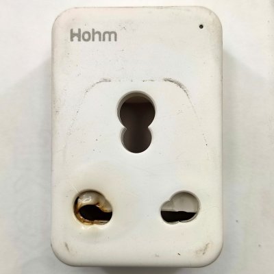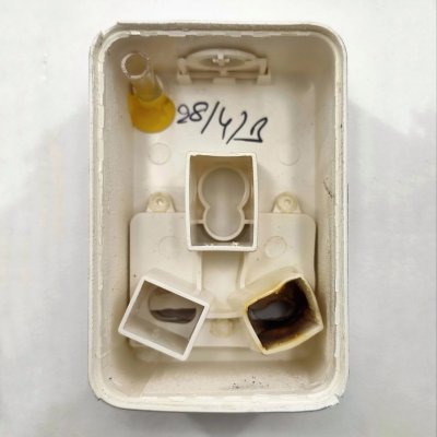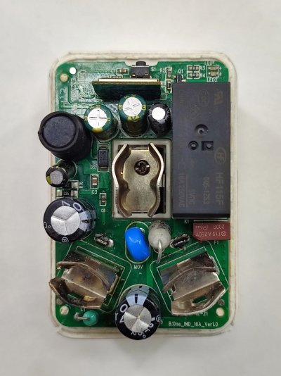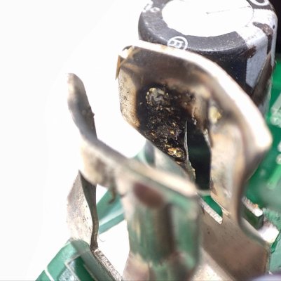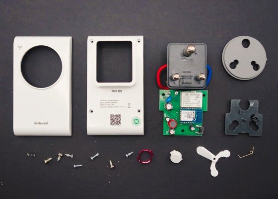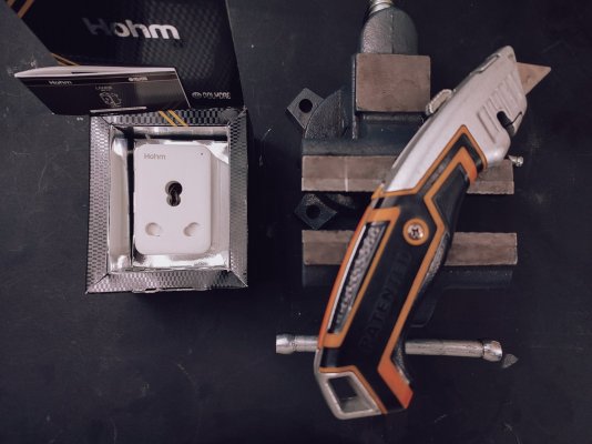
This is a teardown and a guide about preparing a Polycab Hohm Lanre 16A Smart Wi-Fi plug model SLV1910001 for a Tasmota installation.
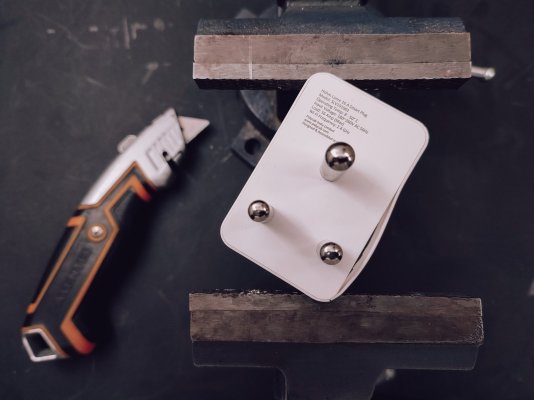
A heavy vise can be used to clamp down opposing corners, the compression will cause the casing to separate.
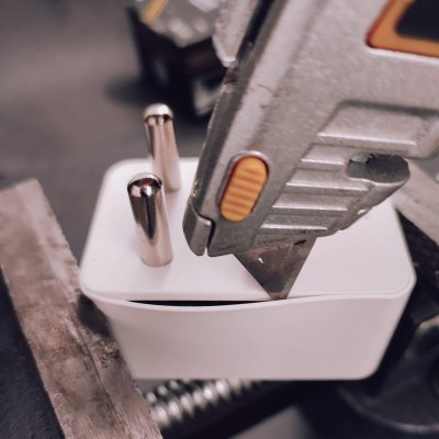
The tip of a box cutter can then be run around the edges to help separate the casing more.
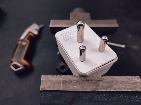
Further the separation by clamping down the other two opposing corners. Run the box cutter one more time and the bottom of the casing should separate cleanly.
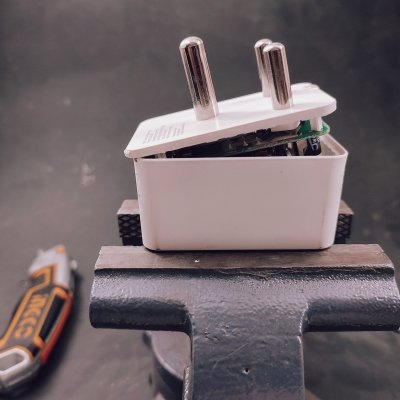
It takes a considerable amount of force but the bottom edge can be lifted up to separate the casing completely.
This pivoted motion is not advised for the 10A version, that model has an electrolytic capacitor along the bottom edge of the pcb that will almost certainly break away. For that model, pivot along one of longer edges.
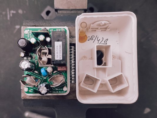
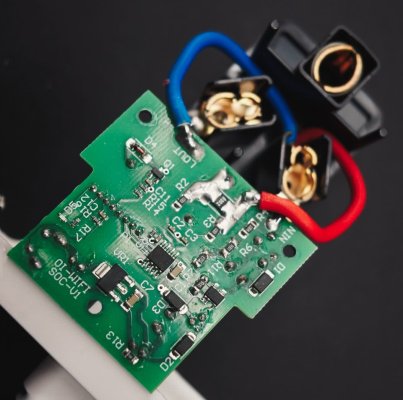
The next sequence of steps is to slice away at the heat-staking and desoldering the two input pins to separate the pcb from the bottom casing.
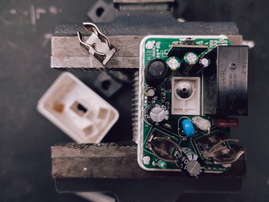
Start with removing the earth pin receptacle which is simply unscrewed. It's very easy to overlook this step when reassembling the plug. Store the screw and receptacle in the larger housing so you remember to reattach it before sealing up the casing.
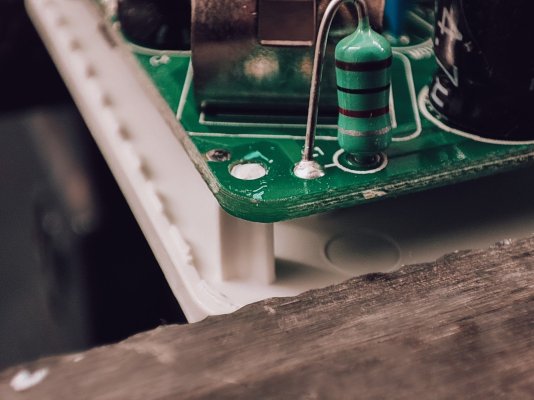
There are four heat-staked supports, each one needs to be cut away cleanly.
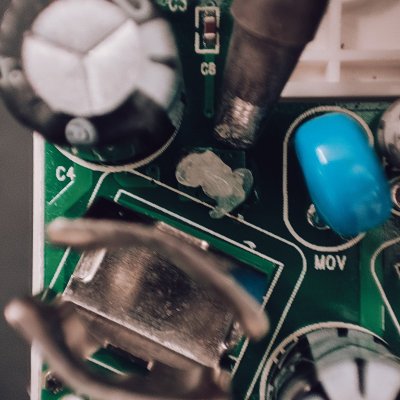
The left pin is the easier one to desolder, so it's a good place to start. A generous blob of flux helps with melting the solder. This is made easier with temperature of the soldering iron set to 350C.
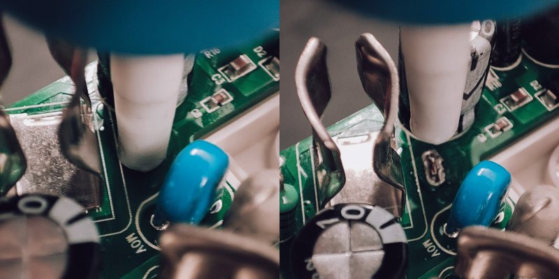
A desoldering pump (solder sucker) removes most of the solder, you'll need to do a few cycles of melting and pumping.
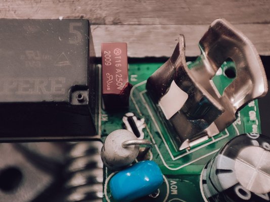
The right pin area is crowded with a few components. Sometimes you can insert the soldering iron straight down, sometimes this ends up melting a nearby component like the fuse here. Bending the pin receptacle gives you a little extra working space.
Once the solder is molten, the pcb can be wriggled free. A heavy vise makes for a good third hand in this situation.
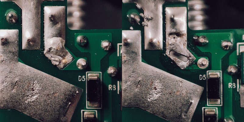
With the pcb free, it's a good time to go in clean up the holes with the desoldering pump to make reassembly easier.
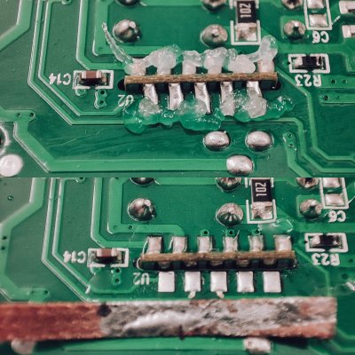
Next up is removing the wifi module. For this, a generous amount of flux and a desoldering wick is essential. Soldering temperature should be lowered to 260C to minimize damage to the pads.
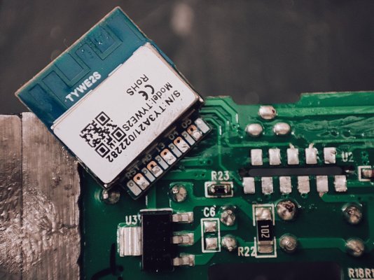
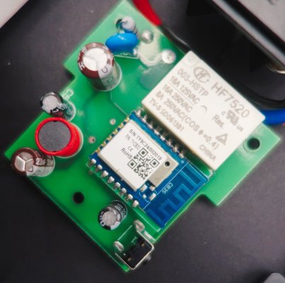
This smart plug uses the Tuya TYWE2S module, which can be directly flashed with Tasmota using an usb serial programmer.
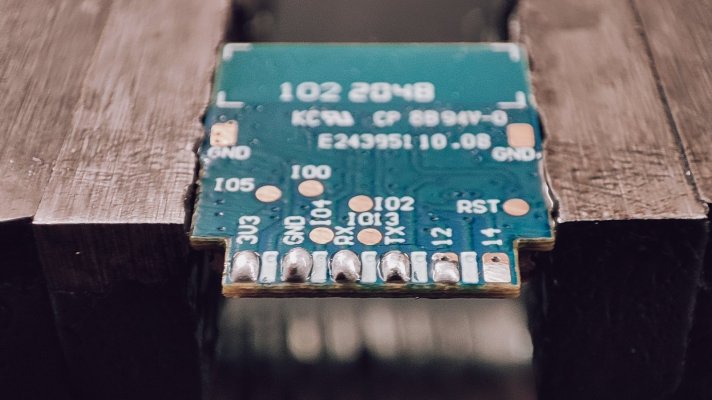
Some kind of programming jig would probably make sense in the longterm but for now we can prep the pads for connecting the programmer with a little excess solder.
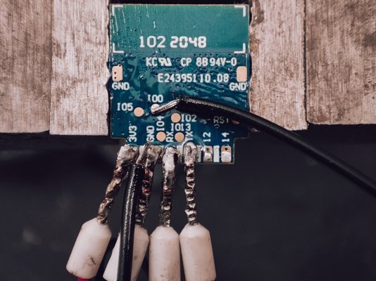
It's not pretty but it works. Flashing is a simple process with Tasmota's web installer. Be sure to erase the device when asked.
Once flashing is complete, disconnect the wire from gpio0 and reconnect the programmer to usb to power up the module. Use a mobile device to connect to the ad-hoc wifi access point created by Tasmota (prefixed with the name tasmota). Your device will then prompt you to sign-in, in actuality you'll be configuring the wifi credentials for the smart plug to connect to your wifi network.
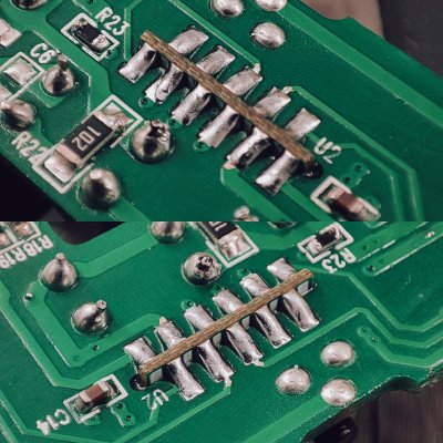
When reinserting and soldering down the module, be certain there are no shorts between adjacent pads. Check for this using a multimeter with its continuity mode.
The plug can be then reassembled for testing without soldering the input pins or sealing the casing. Navigate to the ip address assigned to the plug and paste in the template command from below into the web console and press enter:
template {"NAME":"SLV1910001","GPIO":[0,0,0,32,2720,2656,0,0,2624,576,224,0,0,0],"FLAG":0,"BASE":18}Navigate to Configuration and then Configure Module and select SLV1910001 (0) which should now be at the top the list and then tap on Save. This should prompt a reboot after which your tasmotized wifi plug is ready to use.
Finish with resoldering the pins, bending back the right pin receptacle, reinstalling the earthing pin receptacle and resealing the casing with your favourite low viscosity adhesive. Flex Kwik works well, allow a few minutes to cure.
The next step now is to calibrate power monitoring.


