Teardown & Rebuild of a MuscleGrid LiFePO4 Server Rack Battery
- Thread starter rsaeon
- Start date
You are using an out of date browser. It may not display this or other websites correctly.
You should upgrade or use an alternative browser.
You should upgrade or use an alternative browser.
nithishsabapathi
Explorer
1. Yes, SoH is the measure of the capacity left in the battery.
- SoH, state of health, does this mean how much of the original capacity is left? Like, are my calculations correct? If a 105Ah cell tested at 104.689Ah, then is it correct to say it is at (104.689/105) x 100 = 99.7% State of Health?
- SoC, state of charge, would this be calculated at rated capacity of 105Ah or tested capacity of 104.689Ah?
2. SoC will be calculated for the available capacity (in your case-104.68 ah)
rsaeon
Innovator
1. Yes, SoH is the measure of the capacity left in the battery.
2. SoC will be calculated for the available capacity (in your case-104.68 ah)
Thanks! I needed to know for when I make my own BMS and do some kind of coloumb counting to get SoC numbers for the whole pack.
I'm guessing the SoH for the entire pack would be updated only when it is discharged enough to have one of the cells reach 2.5V.
So 48v 160ah lifepo4 will have 15 cells right and we can re-arrange it to 24v and higher AH, will that give longer run time if running 1kw plus load.
Actually, that pack may be 16S, there's a repair video of a smaller 86Ah pack on YouTube and I think I counted 16 cells. Also the specifications on the side say it's a 51.2V pack, which implies 16S (3.2 x 16 is 51.2)
So you could rewire it as a 8S2P pack for 24V at 320Ah for a 24V inverter, using a quality BMS.
nithishsabapathi
Explorer
OT- Are there any cheap battery capacity testers for 60v battery packs?
I want to check the capacity of my e-scooter battery, getting really bad range these days.
I want to check the capacity of my e-scooter battery, getting really bad range these days.
rsaeon
Innovator
OT- Are there any cheap battery capacity testers for 60v battery packs?
I want to check the capacity of my e-scooter battery, getting really bad range these days.
Cheapest way is to connect 5 identical new headlight bulbs together for a 60v load and connect that to your battery pack after a full charge.
Then time it to see how long it takes until the BMS cuts power.
If you're using 90w bulbs, then that's 90 / 12 = 7.5 amps, and if the pack lasts for 5 hours, then that's a 7.5 x 5 = 37.5Ah.
Have a voltmeter or a multimeter to check voltages every half hour or so to make sure it's not discharging lower than the safe limit. For a 60v/20S LifePO4, that's 50V. I don't know what it is for Lithium Ion.
nithishsabapathi
Explorer
Thanks for the suggestion, for the lower voltage protection, the BMS will cut off the pack at the set low voltage right?Have a voltmeter or a multimeter to check voltages every half hour or so to make sure it's not discharging lower than the safe limit. For a 60v/20S LifePO4, that's 50V. I don't know what it is for Lithium Ion.
Won't the battery tester work for this purpose since i saw it rated for 120v??
rsaeon
Innovator
Thanks for the suggestion, for the lower voltage protection, the BMS will cut off the pack at the set low voltage right?
Won't the battery tester work for this purpose since i saw it rated for 120v??
Yes, the BMS should have a low voltage cutoff. I'm not familiar with EV packs but any Lithium chemistry should not degrade noticeably within three years of daily charging and discharging, so in your case it could be a wonky BMS.
Also yes, the battery tester linked above would work fine for this and it'll be quicker with a 20A discharge but it's 3500. If you go this route and don't want to keep it after you're done, I'd be interested in buying it — I need another one of these.
Would you happen to know if this Muscle grid battery has a PC software which can be connected using the RS485 communication and if there is a RS485 cable that works with it? since I see these ports are available on it. I have this exact same battery purchased a month ago and it came dented exactly as your picture showed with a 15s config. I use a Victron 48v Mppt charge controller to charge it via solar panels on a daily basis and run it at night till morning running an AC through the night. I also use a Victron Smart shunt to coulomb count the AH and get around 100Ah and the state of charge. Both the charge controller and the smart shunt are hooked up to home assistant to automate turning on/off my inverter which is a Delta2 - I use this extra battery to give me more hours of backup during the night. Though I would like to know if I can use PC software to give me the readings of the individual 15 cells and the State of charge and tweak the parameter cell values if need be. The pic below helps me monitor the battery and my inverter when away from home. I would like to also see the individual cell voltages if i can get the PC software to connect with this battery.

rsaeon
Innovator
These 2kv online ups are very hard to find, new ones are quite costly.
Yeah, I'm going to try with a UTL Inverter instead.
I also use a Victron Smart shunt to coulomb count the AH and get around 100Ah and the state of charge.
Thanks for the data point, it's very helpful to know.
Would you happen to know if this Muscle grid battery has a PC software which can be connected using the RS485 communication and if there is a RS485 cable that works with it?
I haven't personally tried it but someone has posted details on how to do this on another forum:
That is for the Shinwa LM-M01A BMS with Narada cells, which is what I found in this battery.
You might need an account on that forum to download attachments. There's another windows app linked that thread called "BMS ND Gyro" that may or may not work:
That thread also has a discussion on how to wire it up to a USB to RS 485 adapter.
Have got in touch with reseller for ups. Will be discussing with him. Got a quote of 3500 for 2kva Emerson MT/Numeric/BP UPS and 4k for APC src model 96v one. Don't know if price is good or what but seems fine to me considering can't find other modelsYeah, I'm going to try with a UTL Inverter instead.
3500 inr for 2kva Emerson MT ups? Used? Even if used, 3.5k is very, very cheap.Have got in touch with reseller for ups. Will be discussing with him. Got a quote of 3500 for 2kva Emerson MT/Numeric/BP UPS and 4k for APC src model 96v one. Don't know if price is good or what but seems fine to me considering can't find other models
Will be checking with him3500 inr for 2kva Emerson MT ups? Used? Even if used, 3.5k is very, very cheap.
rsaeon
Innovator
I reworked the charger a bit and made a few changes with 7 AWG wires:
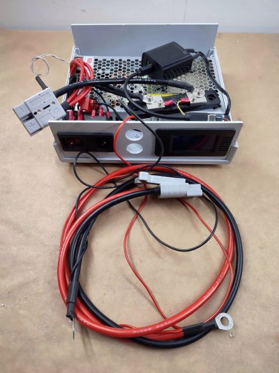
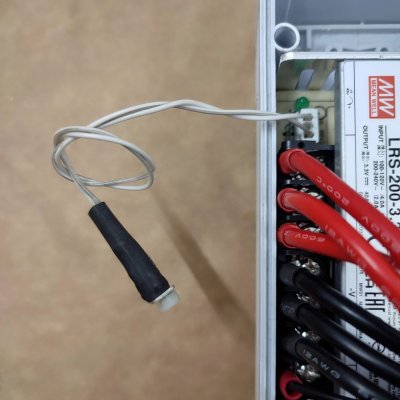
Removed the trimpot and extended it with a simple three-pin/two-wire JST connector:
I was able to measure out a few values for adjusting the output voltage:
I'll probably use a 5-way rotary switch to switch between the different voltages since this isn't a CC power supply and OCP trips in if the voltage is not gradually increased during charging.
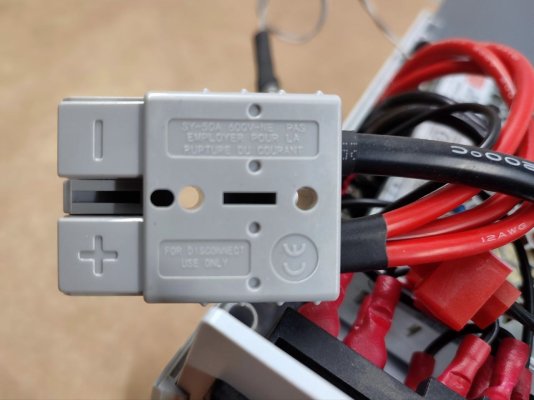
The cables are now crimped with Anderson SB50 connectors:
And the PZEM-015 module is now powered through a USB Type-C power adapter that's connected a USB-PD "decoy" module that outputs 12V:
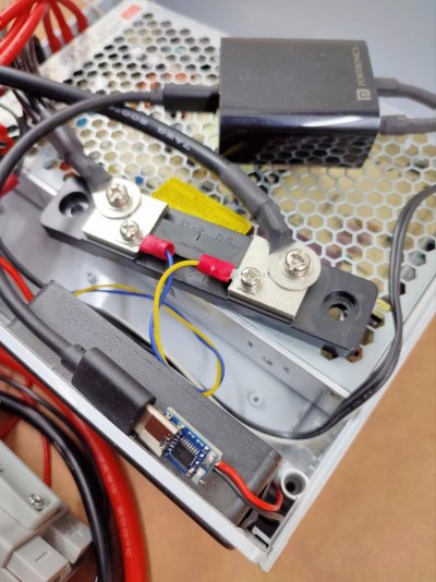
This solution was actually more cost-effective than a dedicated 12V+5V power supply (the power adapter is a dual port one, I might want to add a ESP8266 module to this in the future).
Link for the module: https://quartzcomponents.com/produc...book-9v-12v-15v-20v-pdc004-pd-board-12v-model
The load tester also got new cables, I repurposed the 12 AWG wires I used previously for the charger:
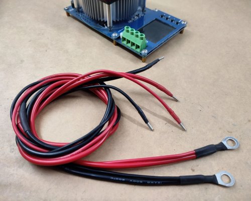
Looks nice and tidy now:
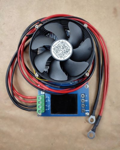
I didn't have smaller gauge wire for the voltage sense wires, so I just ended up using the 20 AWG I had for another project. These are all silicon insulated wires.
Then I made probably the largest non-EMI purchase in recent years, four brand-new 105Ah LiFePO4 cells from MDS Enterprises:
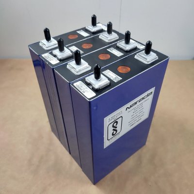
That's because they had a minimum order quantity of 4. These are Narada FE105 cells, and are almost the same size (they're not as tall). I'll be taking out three of the weakest cells from the MuscleGrid pack and adding in these four to make my own 16S pack.
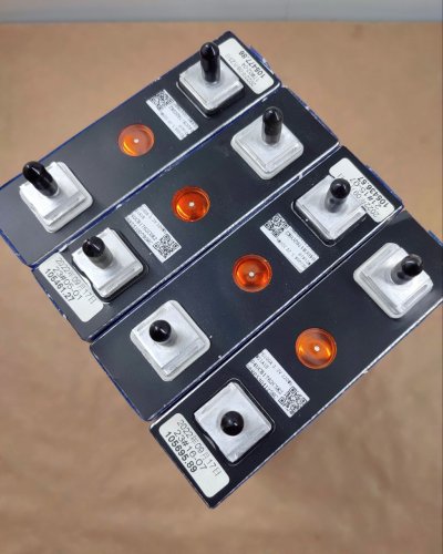
They come pretested, which is nice. The black terminal is positive, while the white terminal is negative.
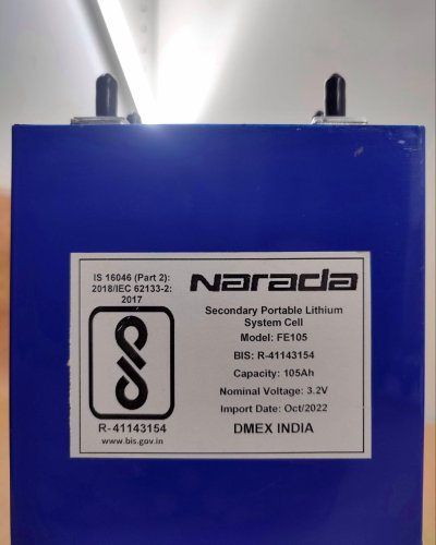
All four added up to Rs 17540 with shipping, I'm still coming to terms with that. My family tells me there's more to life than LiFePO4 cells (ha) while the internet tells me it's okay if hobbies get expensive every now and then. I'm just hoping it all works out in the end and this'll end up serving as a long term battery backup solution, a few months of daal-chawal in exchange for a few years of service from this pack should be worth it.
Next is to top up these cells and do capacity testing. It'll be interesting to see how much charge and/or capacity was lost since these were last tested in September 2022 before being imported.

Removed the trimpot and extended it with a simple three-pin/two-wire JST connector:

I was able to measure out a few values for adjusting the output voltage:
| 166 Ω | 3.65 V |
| 569 Ω | 3.40 V |
| 963 Ω | 3.20 V |
| 1.45 KΩ | 3.00 V |
I'll probably use a 5-way rotary switch to switch between the different voltages since this isn't a CC power supply and OCP trips in if the voltage is not gradually increased during charging.
The cables are now crimped with Anderson SB50 connectors:

And the PZEM-015 module is now powered through a USB Type-C power adapter that's connected a USB-PD "decoy" module that outputs 12V:

This solution was actually more cost-effective than a dedicated 12V+5V power supply (the power adapter is a dual port one, I might want to add a ESP8266 module to this in the future).
Link for the module: https://quartzcomponents.com/produc...book-9v-12v-15v-20v-pdc004-pd-board-12v-model
The load tester also got new cables, I repurposed the 12 AWG wires I used previously for the charger:

Looks nice and tidy now:

I didn't have smaller gauge wire for the voltage sense wires, so I just ended up using the 20 AWG I had for another project. These are all silicon insulated wires.
Then I made probably the largest non-EMI purchase in recent years, four brand-new 105Ah LiFePO4 cells from MDS Enterprises:

That's because they had a minimum order quantity of 4. These are Narada FE105 cells, and are almost the same size (they're not as tall). I'll be taking out three of the weakest cells from the MuscleGrid pack and adding in these four to make my own 16S pack.

They come pretested, which is nice. The black terminal is positive, while the white terminal is negative.

All four added up to Rs 17540 with shipping, I'm still coming to terms with that. My family tells me there's more to life than LiFePO4 cells (ha) while the internet tells me it's okay if hobbies get expensive every now and then. I'm just hoping it all works out in the end and this'll end up serving as a long term battery backup solution, a few months of daal-chawal in exchange for a few years of service from this pack should be worth it.
Next is to top up these cells and do capacity testing. It'll be interesting to see how much charge and/or capacity was lost since these were last tested in September 2022 before being imported.
rsaeon
Innovator
I wired up a 5-way fan regulator switch with a few resistors from a resistor kit just to see how usable it would be:
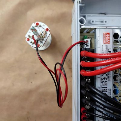
I'm thinking a potentiometer would be a better solution to finely adjust the voltage based on amperage to stay under the 40A limit. Or maybe even finally learn about arduino and have a small microcontroller automatically adjust a digital pot — that would be pretty awesome.
Always exciting to see 40A charging:
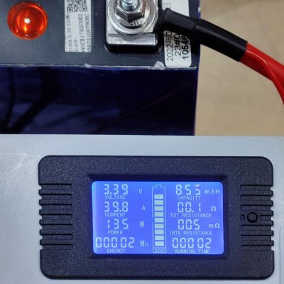
The capacity testing finished, the numbers didn't look right so I did it again and they still aren't close to what I was expecting:
Putting aside that these cells were not top balanced before shipping (even though MDS Enterprises claims they do), the capacity testing results are not indicative of 'Grade A' cells — they're just average, just like the rest of the 'C grade' cells inside the MuscleGrid pack.
Either this is as good as you can expect from cells manufactured by Narada Power or there's an issue with my testing methodology. The variances in the second charge is indicative of something not being right (how do you drain 103Ah, put in 98Ah and get 103Ah back out of a 105Ah cell?). The first two cells were tested in a much warmer climate compared to the other two, I'd say a difference of over 10 degrees, so that might be the reason.
The numbers between the two capacity tests are close enough to rule out wiring inadequacies or insufficient contact. So the discrepancy in the full charge numbers might be within the margin of error of data collection (I did not reset the current meter between cells the second time around, the numbers were calculated cumulatively with a resolution of 1Ah vs 0.1Ah in the initial charge).
Aside from that mystery, it's not very confidence-inspiring to learn that cells that were tested 20 months ago as 105Ah by the manufacturer and presumably were kept in storage the entire time by the importer now measure between 101.5Ah to 103Ah (let's say an average of 102.5Ah). That's a loss of around 1.5Ah per year of storage or a decrease of 1.5% SoH per year.
Is this good, or bad? Looks like I have some research ahead of me.

I'm thinking a potentiometer would be a better solution to finely adjust the voltage based on amperage to stay under the 40A limit. Or maybe even finally learn about arduino and have a small microcontroller automatically adjust a digital pot — that would be pretty awesome.
Always exciting to see 40A charging:

The capacity testing finished, the numbers didn't look right so I did it again and they still aren't close to what I was expecting:
| +Ah to 3.65V (initial charge) | -Ah to 2.5V (1st test) | +Ah to 3.65V (full charge) | -Ah to 2.5V (2nd test) | |
| Cell #1 | 67.9 Ah | 103.108 Ah | 98 Ah | 103.035 Ah |
| Cell #2 | 73.2 Ah | 101.501 Ah | 99 Ah | 101.574 Ah |
| Cell #3 | 67.6 Ah | 103.062 Ah | 100 Ah | 103.100 Ah |
| Cell #4 | 74.4 Ah | 102.713 Ah | 101 Ah | 102.163 Ah |
Putting aside that these cells were not top balanced before shipping (even though MDS Enterprises claims they do), the capacity testing results are not indicative of 'Grade A' cells — they're just average, just like the rest of the 'C grade' cells inside the MuscleGrid pack.
Either this is as good as you can expect from cells manufactured by Narada Power or there's an issue with my testing methodology. The variances in the second charge is indicative of something not being right (how do you drain 103Ah, put in 98Ah and get 103Ah back out of a 105Ah cell?). The first two cells were tested in a much warmer climate compared to the other two, I'd say a difference of over 10 degrees, so that might be the reason.
The numbers between the two capacity tests are close enough to rule out wiring inadequacies or insufficient contact. So the discrepancy in the full charge numbers might be within the margin of error of data collection (I did not reset the current meter between cells the second time around, the numbers were calculated cumulatively with a resolution of 1Ah vs 0.1Ah in the initial charge).
Aside from that mystery, it's not very confidence-inspiring to learn that cells that were tested 20 months ago as 105Ah by the manufacturer and presumably were kept in storage the entire time by the importer now measure between 101.5Ah to 103Ah (let's say an average of 102.5Ah). That's a loss of around 1.5Ah per year of storage or a decrease of 1.5% SoH per year.
Is this good, or bad? Looks like I have some research ahead of me.
Did you specifically ask for Narada Power cells? I had also contacted MDS Enterprises recently and surprisingly they didn't have any EVE cells in stock and most cells were only available as pre-orders. I am confused if I should go with another vendor who seems to be giving a rate of 3000+ shipping for EVE 100 AH cells.
rsaeon
Innovator
Yes, I specifically asked for Narada Power cells so that I could use them with the MuscleGrid cells to make a 16S pack.
If you're looking for new cells, pre-order sounds like the best way, otherwise you'll end up with older cells like mine that you paid a premium for, but end up having less than 100% SoH from prolonged storage.
For comparison, I was quoted Rs 2000 for used cells, Ganjeng 86Ah by rojgarbox.com. That price difference makes used the better buy for an inverter — unlike in a solar or automotive setting where you'd see a full discharge and recharge cycle every day so you'd prefer new cells there.
rsaeon
Innovator
I'm also considering adding a ESP8266+INA219+Relay to cut off power automatically at 3.66V volts.
Looks like I'll need some kind of adjustment knob on the front panel that'll adjust voltage between 3V and 3.65V. Maybe even some kind of automated CC controller with... well it gets complicated now. Knob would be easier.
Or maybe even finally learn about arduino and have a small microcontroller automatically adjust a digital pot — that would be pretty awesome.
I did it! Like wow:
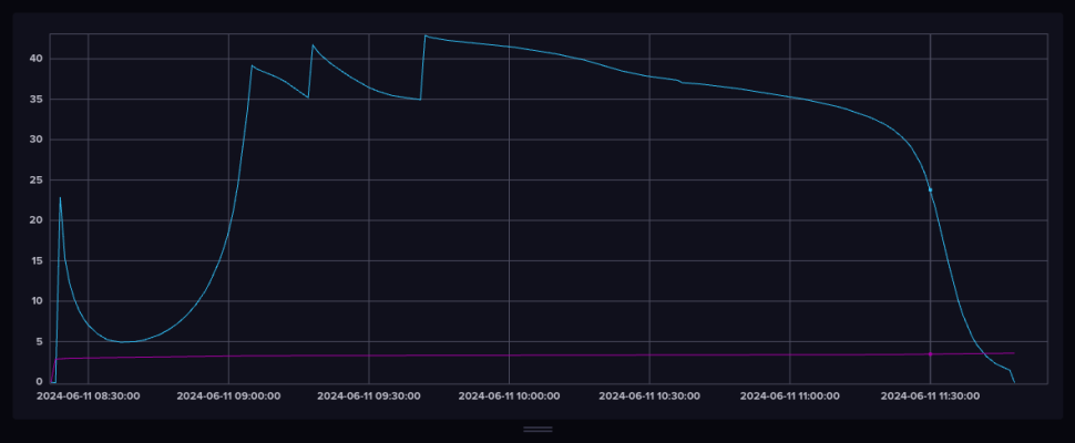
Look at those beautiful curves! I turned this charger into a pseudo constant-current one, haha.
It took around Rs 750 in electronics modules. An ESP8266 module, two INA219 modules (one for voltage, one for current), a X9C103S 10k digital pot, and a 5V relay module. The INA219 does high-side current sensing because it doesn't have a separate VBUS pin but the PZEM module I'm using does low-side current sensing. I'm reusing the PZEM's 50A 75mV shunt (it's 1.5 milliohms) after removing the INA219's current sense resistor. Node-RED combines both readings into a single measurement and logs it to InfluxDB, which is where that graph is from.
I wired up a 1.5k resistor in parallel with the digital pot to get an effective 1.3k sweep, and then wired up a 150 ohm resistor in series with the wiper to get a maximum resistance of 1.45K and minimum of 150E, which lines up close enough to what I needed with the testing I did in a previous post. The digital pot's chip select pin is tied to ground so it never remembers the last setting and always starts in a fresh state.
Tasmota adjusts the digital pot down from 1.45K to 150E until the battery reaches 3.65V through rules/rulesets:
Code:
Rule1
ON System#Init DO BACKLOG Sensor13 0, 0.0015, 0.0015; Power3 1; Rule2 1 ENDON

Rule2
ON INA219-1#Voltage>3.65 DO BACKLOG Power3 0; Rule2 0 BREAK
ON Time#Minute DO BACKLOG Power2 1; Rule3 1 ENDON

Rule3
ON INA219-2#Current>45 DO BACKLOG Power1 0; Power2 0; Rule3 0 BREAK
ON INA219-2#Current<35 DO BACKLOG Power1 1; Power2 0; Rule3 0 ENDON
Rule1 sets the shunt values for both INA219 modules (even though I'm only using one for current sensing), turns on the power and enables Rule2.
Rule2 does two things, it turns off power if 3.65V is reached and then disables itself. Otherwise it'll trigger Rule3 every minute. Part of the trigger is to bring the increment pin high since the digital pot activates on the falling side of the pulse.
Rule3 increments/decrements the voltage (thereby the current flow) by pulsing the digital pot. The decrement part is a safety measure against triggering the over-current protection, it shouldn't ever reach that high in normal operation.
Power1 is wired to the Up/Down pin, Power2 is wired to the Increment pin and Power3 is the relay that has the power supply wired to it's normally-closed contact.
Right now it takes nearly 42mins or 42 pulses of the digital pot to reach any considerable current flow (area under the graph from the beginning to the first 40A peak is just 7.5Ah), so I'll need to refine the code a little. As it is, it's taking 206 minutes to charge up a LFP cell with 100Ah.
Surprisingly, the area under the curve starting from the dot to the end (which is 3.5V to 3.65V) is only 2.11Ah so there's little to gain from charging up to the full 3.65V vs cutting off at 3.5V as some people recommend.
This has been truly exciting, it's probably the cleverest thing I've ever done, woo. I'll share photos of the modules in a later post.
Last edited:
Damn good it looks.I did it! Like wow:
View attachment 198980
Look at those beautiful curves! I turned this charger into a pseudo constant-current one, haha.
It took around Rs 750 in electronics modules. An ESP8266 module, two INA219 modules (one for voltage, one for current), a X9C103S 10k digital pot, and a 5V relay module. The INA219 does high-side current sensing because it doesn't have a separate VBUS pin but the PZEM module I'm using does low-side current sensing. I'm reusing the PZEM's 50A 75mV shunt (it's 1.5 milliohms) after removing the INA219's current sense resistor. Node-RED combines both readings into a single measurement and logs it to InfluxDB, which is where that graph is from.
I wired up a 1.5k resistor in parallel with the digital pot to get an effective 1.3k sweep, and then wired up a 150 ohm resistor in series with the wiper to get a maximum resistance of 1.45K and minimum of 150E, which lines up close enough to what I needed with the testing I did in a previous post. The digital pot's chip select pin is tied to ground so it never remembers the last setting and always starts in a fresh state.
Tasmota adjusts the digital pot down from 1.45K to 150E until the battery reaches 3.65V through rules/rulesets:
Code:Rule1 ON System#Init DO BACKLOG Sensor13 0, 0.0015, 0.0015; Power3 1; Rule2 1 ENDON Rule2 ON INA219-1#Voltage>3.65 DO BACKLOG Power3 0; Rule2 0 BREAK ON Time#Minute DO BACKLOG Power2 1; Rule3 1 ENDON Rule3 ON INA219-2#Current>45 DO BACKLOG Power1 0; Power2 0; Rule3 0 BREAK ON INA219-2#Current<35 DO BACKLOG Power1 1; Power2 0; Rule3 0 ENDON
Rule1 sets the shunt values for both INA219 modules (even though I'm only using one for current sensing), turns on the power and enables Rule2.
Rule2 does two things, it turns off power if 3.65V is reached and then disables itself. Otherwise it'll trigger Rule3 every minute. Part of the trigger is to bring the increment pin high since the digital pot activates on the falling side of the pulse.
Rule3 increments/decrements the current flow by pulsing the digital pot. The decrement part is a safety measure against triggering the over-current protection, it shouldn't ever reach that high in normal operation.
Power1 is wired to the Up/Down pin, Power2 is wired to the Increment pin and Power3 is the relay that has the power supply wired to it's NC pin.
Right now it takes nearly 42mins or 42 pulses of the digital pot to reach any considerable current flow (area from the beginning to the first 40A peak is just 7.5Ah), so I'll need to refine the code a little. As it is, it's taking 206 minutes to charge up a LFP cell with 100Ah.
Surprisingly, the area under the curve starting from the dot to the end (which is 3.5V to 3.65V) is only 2.11Ah so there's little to gain from charging up to the full 3.65V vs cutting off at 3.5V as some people recommend.
This has been truly exciting, it's probably the cleverest thing I've ever done, woo. I'll share photos of the modules in a later post.
rsaeon
Innovator
After some refinements to the code:
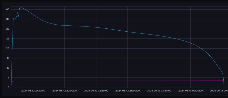
Strangely, it's taking nearly the same amount of time — 204 minutes, but then this is a different kind of LiFePO4 cell. The earlier graph was for the new FE105 cells from DMEX/MDS Enterprises, this graph is for the older FE105C cells from the MuscleGrid battery. I'll retest one of the new cells later on and see if there's any improvement there.
I also changed the way the digital pot was wired up, but first the code:
A quick summary:
Rule set #1 is for code that needs to be run, no matter under what conditions. So it's setting the Shunt Resistor value (Sensor13), turning on the power (Power3), bringing the increment pin high (Power2), turning on the second rule set, turning off the third rule set, and setting the MQTT update period to 10 seconds for finer granularity in the reporting/graphs. The over-current protection is also in this rule set.
Rule set #2 does three things, and they all need to be disabled if the battery is fully charged. The first is the high voltage cut off and changing the MQTT update period to 60 seconds since there's not much that needs to be recorded after a full charge. The command is extra long because we're turning off all the outputs as a visual aid in the webui that charging is complete. The second is to increment the voltage (thereby the current flow) when Rules#Timer=1 ends. The third is to activate Rule set #3 every minute.
Rule set #3 does two things, the first is nothing at all, stop and do not proceed, if current is over 36A (90% of the rated output). Otherwise, it'll trigger Rules#Timer=1 with a duration of 1 second.
This loop of Rules#Timer=1 between the second and third ruleset is necessary to slow down the incrementation, otherwise it'll increment as fast as the sensor refreshes which may overload the microcontroller or trigger the OCP before feedback is recorded by the INA219 sensor. Without this delay, it'll go through all of the hundred steps of the digital pot in 76 seconds. With this one second delay, it's lengthened to a few minutes.
The proto-prototype:
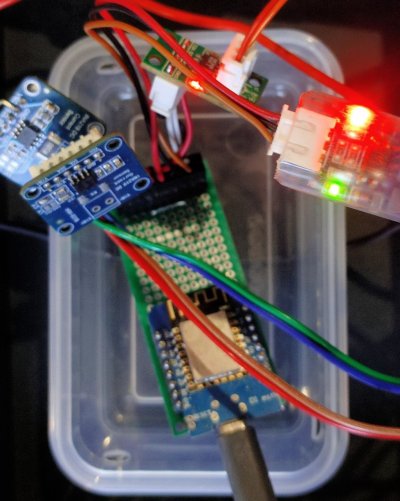
That's the Wemos D1 mini on a prototyping pcb in a little food container.
These are the two INA219 modules:
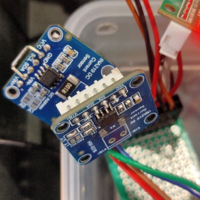
The trace of VIN- is cut in one of them and that pin is shorted to ground for easier wiring directly from the 6 pin header to the output of the power supply. This also ties the ground of the power supply with the ground of the ESP8266 module, necessary to measure the voltage.
The other module has the shunt resister removed and the I2C address changed with a solder blob. Tasmota recognises the unmodified module as 1 and the modified one as 2, it can recognize upto four (short A1 instead of A0 for the 3rd and short both A0 and A1 for the 4th).
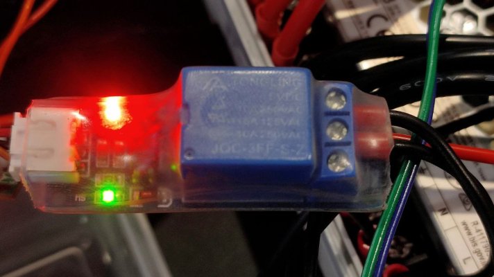
The 5V relay module is covered in transparent heatshrink for safety, this module has a physical cut in the PCB separating the high side from the low side.
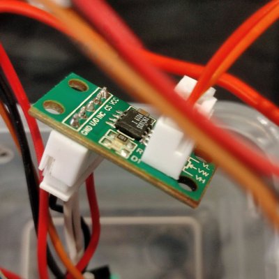
This is the digital pot module, I love this thing:
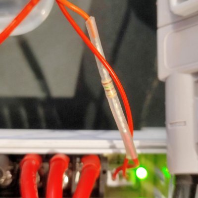
And the inline resistor to make sure the voltage doesn't exceed the safe maximum (lower the resistor = higher the voltage, so when the digital pot is at 0, the minimum resistance is 150E, which is this resistor):
The digital pot X9C103S is 10k from end to end, with 100 steps. The wiper has a separate resistance of 40E. So each step is 0.1K or 100E. In the previous graph, there were just three increments needed, the last three, so from 97 to 100, to adjust the current flow. That was with three series 510E resisters wired in parallel to the digital pot:
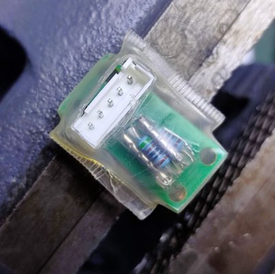
Those last three steps add up to 300E, it would be nice to have more granularity there.
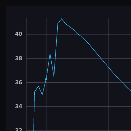
So what I did was tie both ends of the digital pot together, making it appear as if it was two 5k resistors in parallel, this brought the resistance down to 2.5K. So now, the wiper would travel from 0 to 2.5k and back to 0. Each step now is 2500 x 2 / 100 = 50E. A little better, with now 6 steps in a 300E range.
You can see those six steps here as peaks, the dot is one of those six steps:
Then I added a 3.3K resistor in parallel to the wiper and one of the ends, to get the value down to 1.4K. I would like even more steps but this'll do for now.
The CS pin was disconnected from ground and connected to GPIO15 pin. The CS pin, when pulled high, will set a default state for the digital pot. This is needed for calibration since we don't want the voltage going from high to low to high again or vice verse. So I manually toggled the increment pin until I got the lowest voltage and then toggled the GPIO15/CS pin to set that value as the starting point.
I'll revisit this battery charger project later, next is to start making my own Tasmota-based BMS.

Strangely, it's taking nearly the same amount of time — 204 minutes, but then this is a different kind of LiFePO4 cell. The earlier graph was for the new FE105 cells from DMEX/MDS Enterprises, this graph is for the older FE105C cells from the MuscleGrid battery. I'll retest one of the new cells later on and see if there's any improvement there.
I also changed the way the digital pot was wired up, but first the code:
Code:
Rule1
ON System#Init          DO BACKLOG Sensor13 0, 1, 0.0015; Power3 1; Power2 1; Rule2 1; Rule3 0; Teleperiod 10 ENDON
ON INA219-2#Current>46  DO BACKLOG Power1 0; Power2 0; Power2 1; Rule3 0 ENDON


Rule2
ON INA219-1#Voltage>3.6 DO BACKLOG Power1 0; Power2 0; Power3 0; Rule2 0; Rule3 0; Teleperiod 60 BREAK
ON Rules#Timer=1        DO BACKLOG Power1 1; Power2 0; Power2 1; Rule3 1 BREAK
ON Time#Minute          DO Rule3 1 ENDON


Rule3
ON INA219-2#Current>36  DO Rule3 0 BREAK
ON INA219-1#Voltage<3.6 DO BACKLOG RuleTimer1 1; Rule3 0 BREAK
A quick summary:
Rule set #1 is for code that needs to be run, no matter under what conditions. So it's setting the Shunt Resistor value (Sensor13), turning on the power (Power3), bringing the increment pin high (Power2), turning on the second rule set, turning off the third rule set, and setting the MQTT update period to 10 seconds for finer granularity in the reporting/graphs. The over-current protection is also in this rule set.
Rule set #2 does three things, and they all need to be disabled if the battery is fully charged. The first is the high voltage cut off and changing the MQTT update period to 60 seconds since there's not much that needs to be recorded after a full charge. The command is extra long because we're turning off all the outputs as a visual aid in the webui that charging is complete. The second is to increment the voltage (thereby the current flow) when Rules#Timer=1 ends. The third is to activate Rule set #3 every minute.
Rule set #3 does two things, the first is nothing at all, stop and do not proceed, if current is over 36A (90% of the rated output). Otherwise, it'll trigger Rules#Timer=1 with a duration of 1 second.
This loop of Rules#Timer=1 between the second and third ruleset is necessary to slow down the incrementation, otherwise it'll increment as fast as the sensor refreshes which may overload the microcontroller or trigger the OCP before feedback is recorded by the INA219 sensor. Without this delay, it'll go through all of the hundred steps of the digital pot in 76 seconds. With this one second delay, it's lengthened to a few minutes.
The proto-prototype:

That's the Wemos D1 mini on a prototyping pcb in a little food container.
These are the two INA219 modules:

The trace of VIN- is cut in one of them and that pin is shorted to ground for easier wiring directly from the 6 pin header to the output of the power supply. This also ties the ground of the power supply with the ground of the ESP8266 module, necessary to measure the voltage.
The other module has the shunt resister removed and the I2C address changed with a solder blob. Tasmota recognises the unmodified module as 1 and the modified one as 2, it can recognize upto four (short A1 instead of A0 for the 3rd and short both A0 and A1 for the 4th).

The 5V relay module is covered in transparent heatshrink for safety, this module has a physical cut in the PCB separating the high side from the low side.
This is the digital pot module, I love this thing:

And the inline resistor to make sure the voltage doesn't exceed the safe maximum (lower the resistor = higher the voltage, so when the digital pot is at 0, the minimum resistance is 150E, which is this resistor):

The digital pot X9C103S is 10k from end to end, with 100 steps. The wiper has a separate resistance of 40E. So each step is 0.1K or 100E. In the previous graph, there were just three increments needed, the last three, so from 97 to 100, to adjust the current flow. That was with three series 510E resisters wired in parallel to the digital pot:

Those last three steps add up to 300E, it would be nice to have more granularity there.
So what I did was tie both ends of the digital pot together, making it appear as if it was two 5k resistors in parallel, this brought the resistance down to 2.5K. So now, the wiper would travel from 0 to 2.5k and back to 0. Each step now is 2500 x 2 / 100 = 50E. A little better, with now 6 steps in a 300E range.
You can see those six steps here as peaks, the dot is one of those six steps:

Then I added a 3.3K resistor in parallel to the wiper and one of the ends, to get the value down to 1.4K. I would like even more steps but this'll do for now.
The CS pin was disconnected from ground and connected to GPIO15 pin. The CS pin, when pulled high, will set a default state for the digital pot. This is needed for calibration since we don't want the voltage going from high to low to high again or vice verse. So I manually toggled the increment pin until I got the lowest voltage and then toggled the GPIO15/CS pin to set that value as the starting point.
I'll revisit this battery charger project later, next is to start making my own Tasmota-based BMS.
Last edited:


