Working with Inverter/UPS Lead Acid Batteries

I've sunk in 10k with used batteries so far (bought the second one after my last update here) so it's more likely that I'll change the inverter. Maybe do some kind of exchange with a reseller on OLX. Or buy a new inverter on EMI that does have a charge setting/profile for SMF.

Quick update: After a few months of saving and budgeting, that is what I ended up doing. The Luminous Optimus and iCruze inverter models have a SMF battery setting that float charges at 13.45V which is acceptable for the Amaron Quanta batteries.

I sold two of the dead 100ah Quanta batteries for scrap at Rs 3000 each and purchased a physically damaged but perfectly operational 24V Luminous Optimus/iCruze inverter (the lowest tier 2000VA one). It's hooked up to the remaining two used batteries that I purchased about six months ago.

The Optimus and iCruze models have solid state switching when power cuts out, just like the older Cruze+ models, so my entire fleet of systems remain online even at load. But this is a temporary setup until I finish my LiFePO4 battery rebuild (probably by the end of the year) and pair it with my older 48V Luminous Cruze inverter linked in the first post.

The next project would be to see if it's viable to rehouse that 48V Luminous Cruze+ inverter into a rackmount enclosure/form factor.
 
  • Like
Reactions: rahuljawale
The Optimus and iCruze models have solid state switching when power cuts out, just like the older Cruze+ models, so my entire fleet of systems remain online even at load.
I've observed this is only true under controlled outages — like when I turn off the switch at the wall. In actual use, the Luminous Optimus/iCruze 2000VA inverter trips if there's any mains disruption and it abruptly cuts power.

It might be because of the 1kW load. The 3500VA model didn't cut off power with a 1000W load, but this 2000VA model has not been able to maintain power with the same load. At one point it turned off completely with a "Short Circuit" error being displayed and it needed to be manually turned on (we had four power outages yesterday).

So it's clear that this solution isn't working as expected. Weighing the options, the most affordable one is to get the 3500VA inverter back online with four of the cheapest batteries I can find (it's a 48V inverter) and wire that up in between the wall outlet and the 2000VA inverter. This way the 3500VA inverter can serve as a stabilizer/UPS that'll smoothen out mains voltage disruptions while the 2000VA (which has a 24V 100Ah battery bank) can serve as the actual battery backup.

With that decided, I purchased four used Amaron 26Ah without warranty at Rs 1650 each and started charging them up for a capacity test before connecting them to the 3500VA inverter.

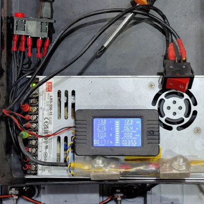
The recent testing with the LiFePO4 cells really puts it into perspective how ancient Lead Acid batteries are as a technology. The 40A charger can charge a 100Ah LFP cell in under 3 hours from flat and the cell will happily accept it. But with these 26Ah AGM/VRLA batteries, wired in parallel and connected to an impromptu +20A charger that I made, charging has been excruciatingly slow:

photo_2024-06-06 09.57.33.jpeg

It's taken four hours to add a paltry 12Ah to the 26x4 = 104Ah batteries! The batteries simply won't accept a faster charge even though this power supply is more than capable.
It would appear that the smarter choice in the beginning would've been not to buy the 24V inverter but to instead buy two more 100Ah batteries to add the two used ones I already had, and connect them to the 3500VA inverter. This would've been also a lower cost option, at about 11000 for two 100Ah batteries vs 6000 + 4x1650 = 12600 for the 2000VA and these four 26Ah batteries. And had I done this six months ago, the two batteries would've costed less at 10000. Prices went up after the change in government here that re-introduced us to multiple daily power cuts.

Penny wise, pound foolish?
 
Last edited:
It's taken four hours to add a paltry 12Ah to the 26x4 = 104Ah batteries! The batteries simply won't accept a faster charge even though this power supply is more than capable.
The only real advantage of Lead acid is that it is cheap and can provide an insane amount of current, like 500amps which is useful for starter motors in vehicles. Apart from that, the chemistry just sucks.

To charge from 0->70% it will need about 7-8 hours [Bulk] (Max current typically < 1C)
To charge from 70->100% it will need another 8-10 hours [Absorption] (Max current typically 0.1-0.2C)
So essentially you're looking at overnight charging.
The higher the SoC, the lower the current you can give it.

This is true even for a tiny 12v battery.
 
  • Like
Reactions: rsaeon
Thanks, I forgot about the different charging stages for LA batteries. I charged them at 13.8V (boost voltage) for 8 hours and then switched to 13.5V (float voltage) and it stabilized at under 0.5A current draw after about half a day.

They each tested at about 6Ah for a 20A current draw down to 10.5V, giving a runtime of 20mins. That's not great but not bad, and honestly it's more than what I need to use that 3500VA inverter as a UPS.

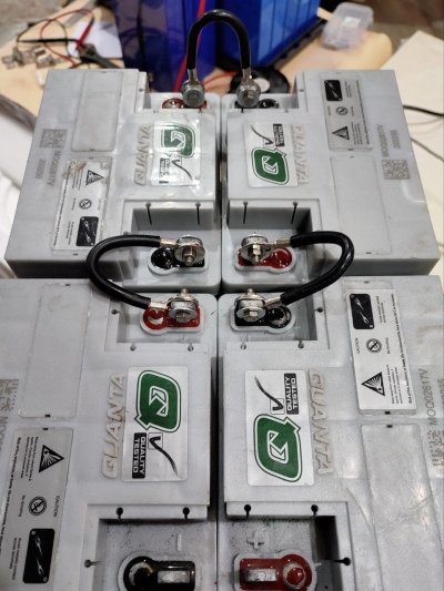
I used some scavenged 10 sq mm from the MuscleGrid battery's BMS to make the connecting cables, since this is essentially a budget/temporary solution I didn't go all out with new hardware or even heatshrink.

Just reused what I had:

photo_2024-06-08 08.45.26.jpeg

Again, this (admittedly attractive aesthetic) layout/configuration is not at all recommended — it's not only dangerous but probably borderline criminal in some countries. Any tool or metallic object could fall in between the terminals and cause a short, leading to a fire.

The terminals should be placed on the outer perimeter of such an arrangement, I didn't have enough wire for that (all connecting cables need to be of equal length).

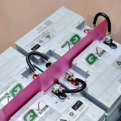
Instead, I put in some plastic sheets from a file/folder as an insulator between the two halves of the battery bank:

photo_2024-06-08 08.45.28.jpeg

I test-dropped some wrenches and screwdrivers on the batteries (never do that) and it worked well, the plastic is tall enough over the batteries that it folds down to one side and completely covers the terminals when something falls down on it.

At some point, I'll make some tasmota-based wifi battery monitors for these since I like having all of that telemetry, but this is the solution for the foreseeable future until I finish building up the LiFePO4 battery (end of year).
 
An unforeseen but obvious complication with a double inverter/ups setup is increased power consumption, I was able to quantify just how much yesterday after a 30 minute power outage.

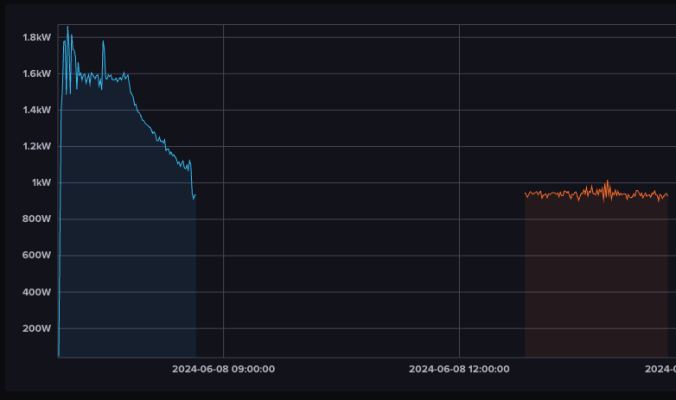
If I understood the numbers correctly, this setup of dual inverters used ~750W of power to recharge the batteries that provided ~450W for an efficiency of 450/750 = 60%.

In absolute numbers, that's an excess of ~300W consumed or Rs 3.5 billed (at Rs 10.5 per kWh) for that ~30min power outage.

Screen Shot 2024-06-09 at 12.07.06 PM.png

Blue being the power draw during charging, orange being typical power draw over the same length of time later on in the day.

I used InfluxDB's integral(unit: 1h) function to calculate the area under these two graphs to get Wh (?) consumption numbers:

normal_field_value_start_stop
Power
1711.57270361111
2024-06-08T12:50:00.000Z
2024-06-08T14:40:00.000Z
charging_field_value_start_stop
Power
2458.78310972222
2024-06-08T06:50:00.000Z
2024-06-08T08:40:00.000Z

So that's 2458 - 1771 = 747W total power used for charging.

Power used during the power outage was derived from the normal usage numbers, 1711W for 110mins works out to be 1711 x 30/110 = 466W for 30mins.

Subtracting that from the power used for charging and we end up with 747 - 466 = 281W excess power consumed during charging.

Or I could be wrong. I got 12/100 in Botany & Zoology so I hope these calculations are at least a little bit correct.
 
  • Like
Reactions: enthusiast29
I will be interested to see how the tasmota-based wifi battery monitor functions . awaiting the detailed build log and would low to try this for my battery bank as well.
 
I will be interested to see how the tasmota-based wifi battery monitor functions . awaiting the detailed build log and would low to try this for my battery bank as well.

 
  • Like
Reactions: swiftwind
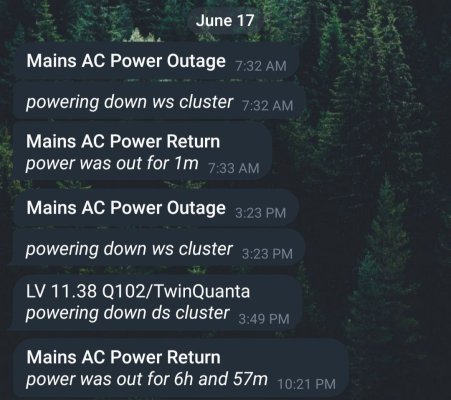
photo_2024-06-17 23.08.15.jpeg

Vindicated! The dual inverter setup performed admirably today.

The non-essential cluster is shutdown immediately during a power outage, while the 1kW cluster is shutdown when either of the two 100Ah batteries falls under 10% SoC (~11.5V) — that's after 26 minutes in the screenshot.

But there was enough power in all three battery banks (1x 100Ah, 2x 100Ah and 4x 26Ah) to run the essential cluster (home wifi, cameras and automation) along with fans and lights for another six and a half hours!

And yeah, we had a 7 hour power outage today. I had to switch over the load of general purpose inverter with a single 100Ah battery (it powers lights and fans) to this setup halfway through. The lights and fans are in my parent's rooms so they were comfortable the entire time, which makes all of this worth it.
 
Last edited:
Any tool or metallic object could fall in between the terminals and cause a short, leading to a fire.
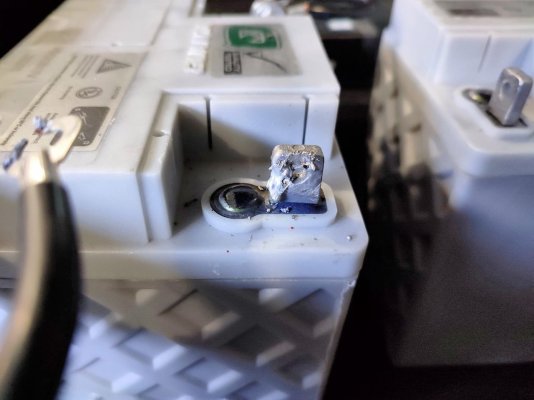
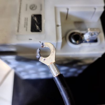
Got a reminder today just how precious life is:

photo_2024-06-19 19.47.17.jpeg


photo_2024-06-19 19.47.21.jpeg

This happened when I was disassembling the battery bank to move it to a different shelf.

I started by disconnecting the connecting wire that's half way in the bank, this is the recommended way as it would break the series batteries in two less dangerous halves.

What I didn't do is not making sure the wire was completely free of the terminal, because just disconnecting isn't enough. Preferably temporarily insulated until the move was done.

So when I went to remove the other connecting wires, the wrench shorted the two halves and this loosely touching terminal arced and melted along with part of the battery terminal.

Of course this happened when I was rushing through the process because I didn't want to be without backup power any longer than necessary.

But then what's the purpose of backup power if you're dead?
 
Preferably temporarily insulated until the move was done.

When I was a kid, I did a lot of damage by leaving exposed wires dangling around. I've now got habitual to immediately tape off the exposed wires. Sometimes I get interrupted and have to leave stuff unattended for a long time. I usually work alone when dealing with electricity and I know no one is going to save me in case of mishaps.

So when I went to remove the other connecting wires, the wrench shorted the two halves and this loosely touching terminal arced and melted along with part of the battery terminal.

This is the exact same way I learned that I could use batteries for welding!
 
  • Like
Reactions: rsaeon
guys is it possible to monitor these inverter batteries water level remotely remotely in sense that it it makes a sound or something when the levels go below a specific level?
 
  • Like
Reactions: rsaeon
The 2kva Luminous inverter I got sometimes trips and shuts off due to overloading, and I needed to monitor that, so I set up a simple ESP32 cam pointed at the display ha. It works well enough but a maybe an actual security camera would be better and cost a little bit more, around 1k.

I guess you could use an ultrasonic sensor to measure the water levels but that might end up costing more since you'd need a sensor for each of the cells and the smaller ones that'll fit inside the fill port are expensive.

there are other water sensors that can sense water at a particular spot or level but again, a camera would be more cost effective.
 
  • Like
Reactions: anmolbhard004
The 2kva Luminous inverter I got sometimes trips and shuts off due to overloading, and I needed to monitor that, so I set up a simple ESP32 cam pointed at the display ha. It works well enough but a maybe an actual security camera would be better and cost a little bit more, around 1k.
Fwiw, you could attempt ML on the video feed such that when the water level drops and the indicator falls below green, you can trip a notification.
images


I'm not sure if an ESP32 can handle this, but a Pi Zero definitely can.
 
  • Like
Reactions: ibose and rsaeon
Fwiw, you could attempt ML on the video feed such that when the water level drops and the indicator falls below green, you can trip a notification.
images


I'm not sure if an ESP32 can handle this, but a Pi Zero definitely can.
any camera from tp link would work?
also you guys can help me in setting this / training on pi zero right?
@rsaeon